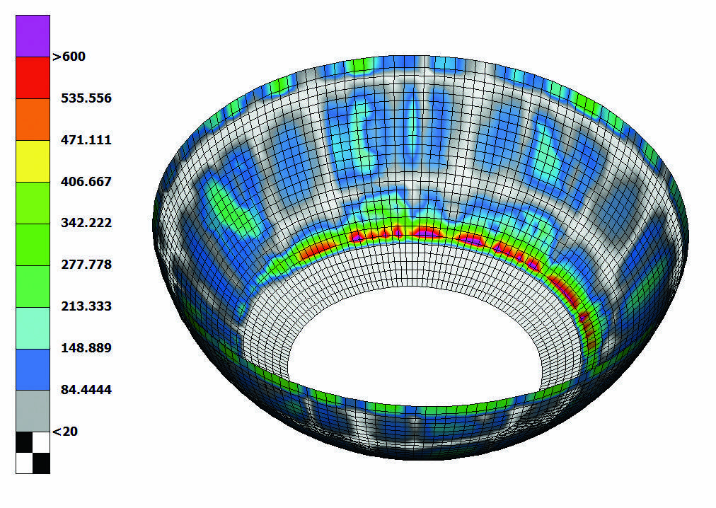
Simulation is an essential part of the design process because full model physical tests are impossible. It also saves valuable time. George Korbetis and Dimitris Georgoulas present three case studies of structural and CFD analyses for offshore structures
1. Introduction
Safety and efficiency are key factors for offshore structures. Such structures operate under harsh environmental conditions[ds_preview] and thus have to withstand extreme weather phenomena. Moreover, as they are usually located close to delicate environments, any possibility of failure or accident should be eliminated.
During the design process of such structures, the extensive use of CAE simulations is often needed in addition to the standard assessment calculations. In most cases offshore and energy production structures are complex and large-scale, thus full model physical tests are not possible. This in turn makes the simulation process imperative. The use of simulation helps to ensure the upfront achievement of the product’s performance characteristics and minimizes the failure risk throughout its lifetime. Furthermore, CAE simulation is an imperative tool for the design of innovative structures and for the use of exotic materials.
The numerical simulation process may prove to be time consuming, since many load cases and disciplines need to be employed to ensure the accurate investigation of the model’s behavior.
The use of highly efficient pre- and post- processing software is essential for the time reduction of engineering analyses. This paper presents how ANSA CAE pre-processor and ETA CAE post-processor fulfill this requirement for the offshore structures industry by offering advanced modelling and results assessment features, enhanced with advanced automation capabilities. Three case studies of structural and CFD analyses for offshore structures are used in this investigation.
2. Structural analysis of a semi-submersible platform
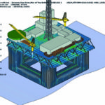
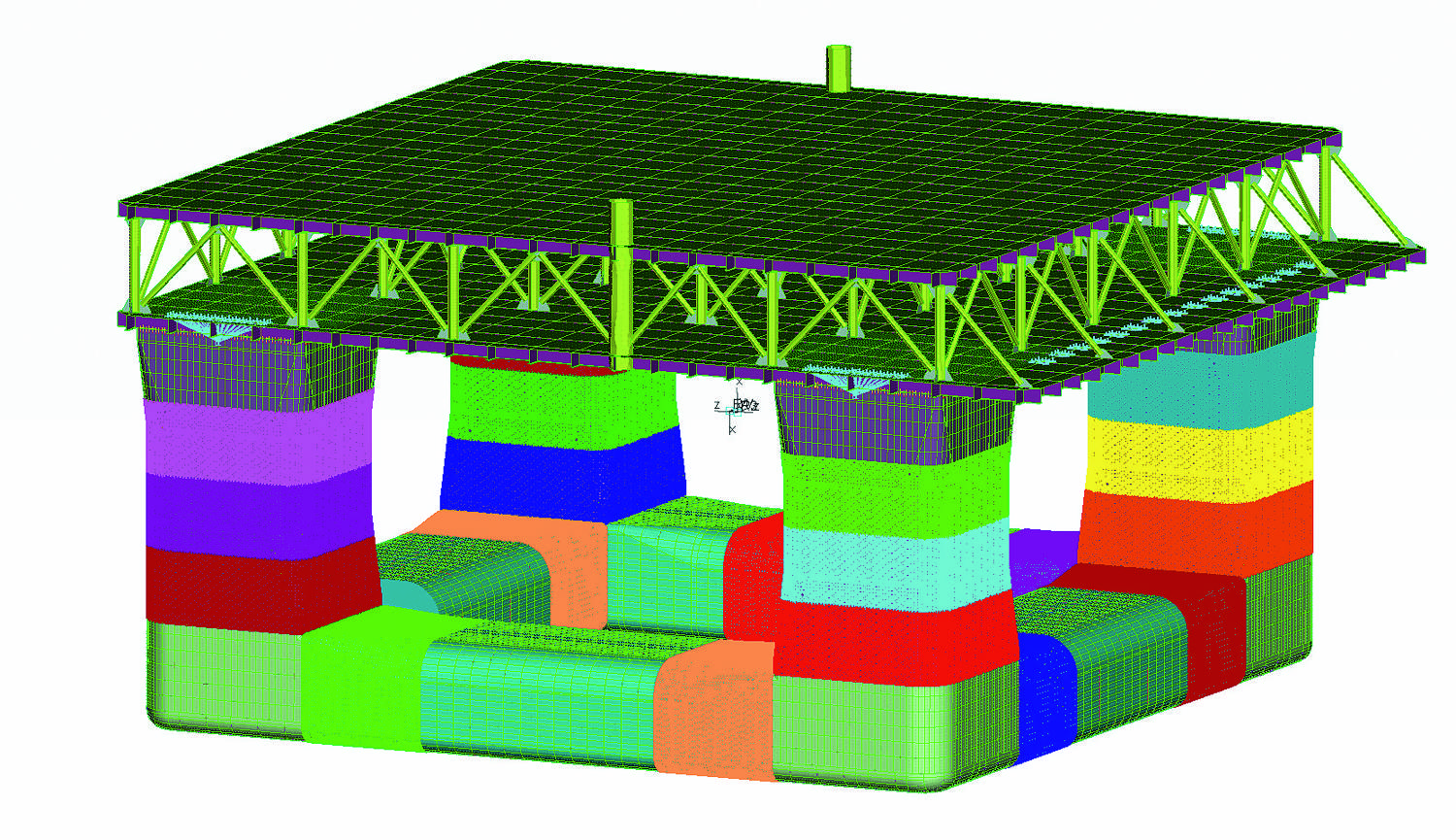
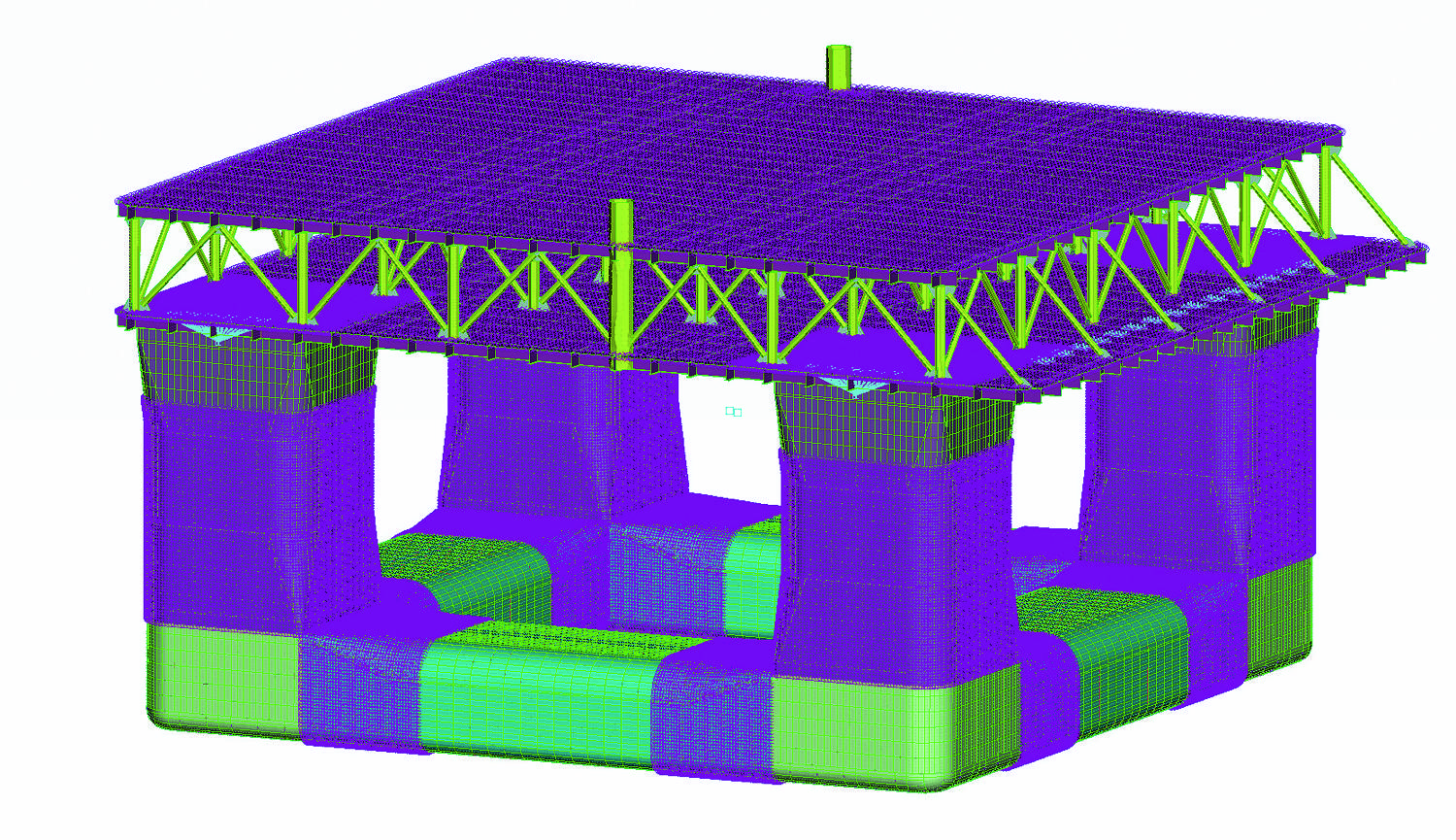
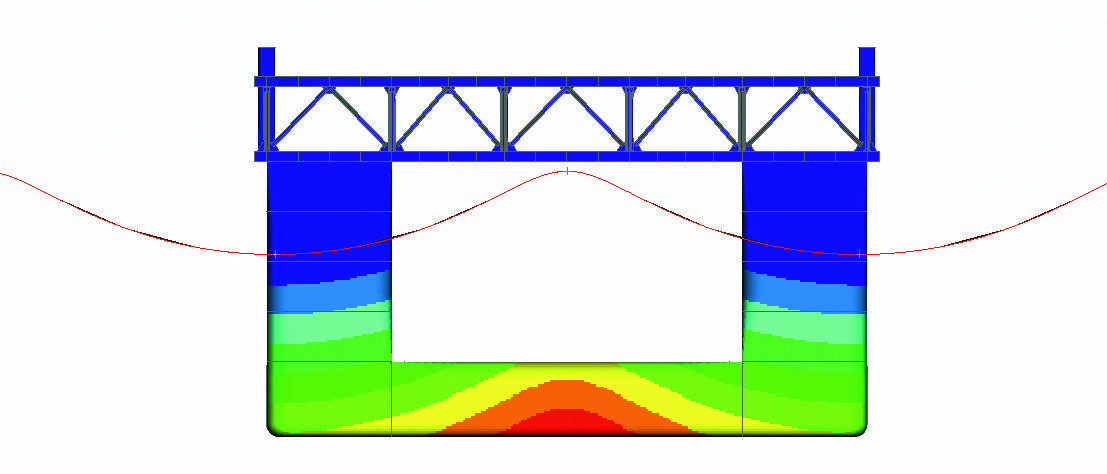
In the first case study a semi-submersible platform is analyzed (Fig. 1). The simulation consists of a static analysis in hogging condition. A 10 m high wave affects the structure while its length is identical to the platform’s length. In this load case the platform is fully loaded, so masses are distributed in the hull, deck and tanks in order to simulate the additional weight of the ballast, production and storage tanks. Mooring and riser lines’ forces were applied at the hull at certain positions. Gravity acceleration was also applied. Finally, buoyancy was applied as hydrostatic pressure on the elements below waterline and varied linearly with water depth.
Special tools of ANSA are used to facilitate the definition of the FE model such as the wave definition tool, the mass balance and the buoyancy application. The ANSA Task Manager provides great assistance in the organization and automation of the above process.
2.1. Process management
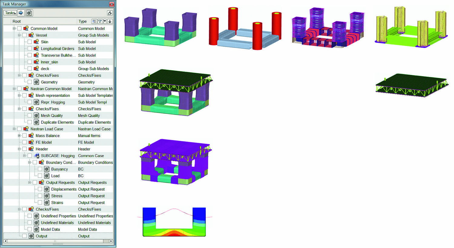
The definition of the platform FE model can be facilitated and automated through the Task Manager tool provided by the ANSA pre-processor (Fig. 2). In this tool, all actions needed to complete an FE model are defined in a stepwise manner. Actions such as geometry handling, meshing and boundary conditions are defined as a Task Item. Then, the Task Manager runs and realizes every Task Item and thus sets up the FE model automatically.
The first step of the FE model set-up process is the gathering of all CAD data of all sub-assemblies in one geometrical model. The sub-assemblies are connected together according to defined connectivity specifications. Meshing is applied at the model at the next step of the Task Manager sequence. Meshing parameters and quality criteria are defined for different areas, parts or assemblies of the model. Then, meshing is applied automatically by the ANSA Bach Meshing tool, which is controlled by the Task Manager. During the batch meshing, geometrical simplifications such as holes’ filling and representation of reinforcements with beams are also performed. At the next steps of the Task Manager, mass and loads – which are described below in detail – are applied. After the definition of all steps, the Task Manager runs and performs one by one every action on the model.
2.2. Model simplification
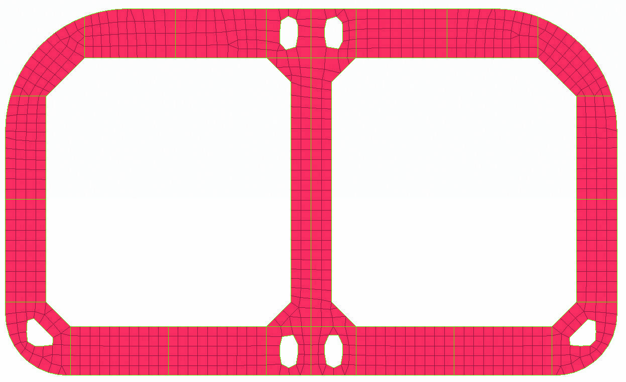
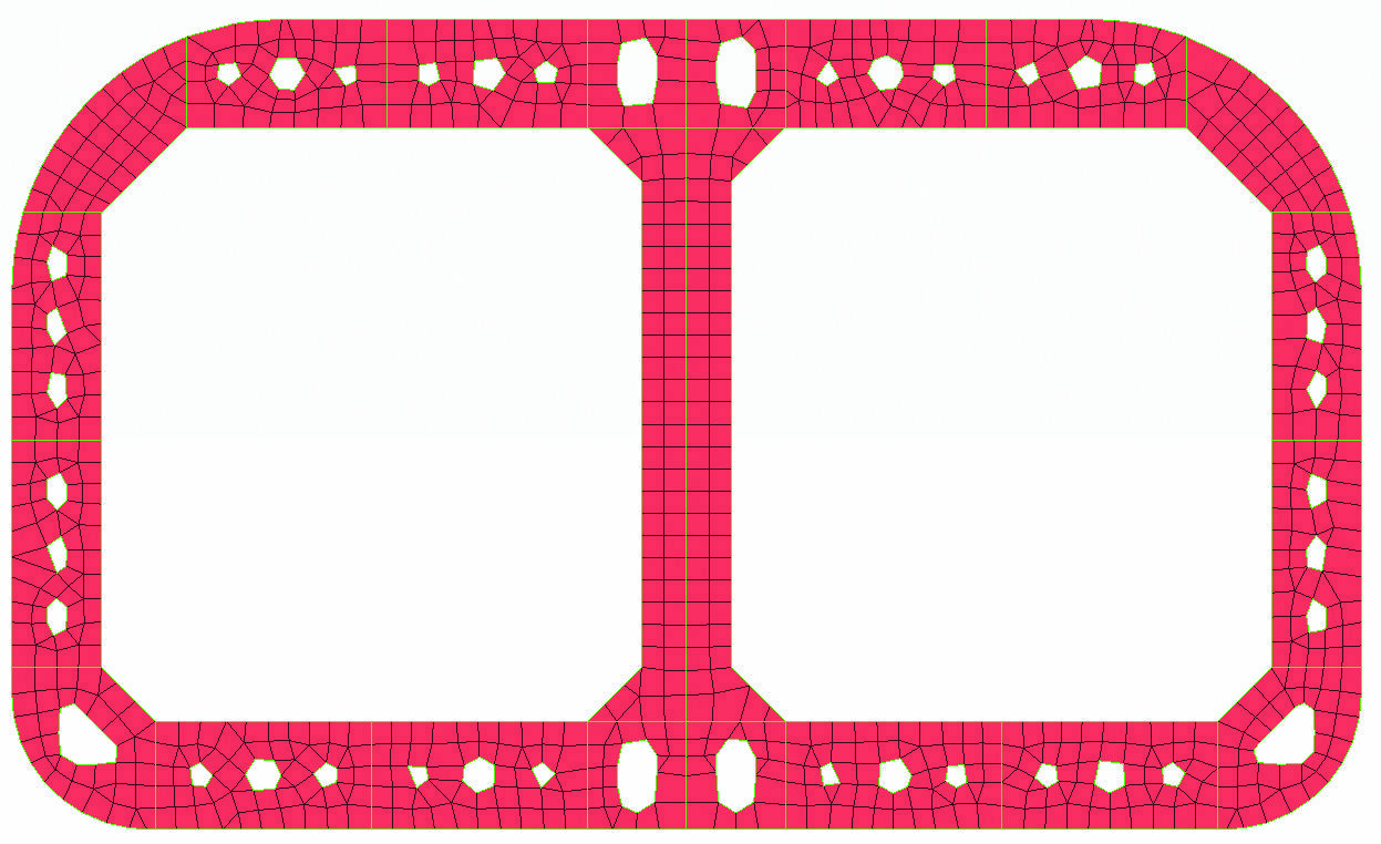
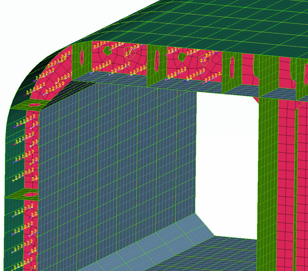
Prior to the application of the mesh, an important step for the model set-up is the simplification of the geometry. This action excludes unnecessary details from the model that do not affect its behavior but still tend to reduce meshing quality. In this case holes with diameter less than a specified value are identified and filled automatically. The model is automatically re-meshed at the filled areas. The hole filling improves the mesh quality and reduces the number of elements and thus the simulation time needed for this analysis (fig. 3). The parameters for the holes’ filling are prescribed at the Batch Meshing action applied to the model by the Task Manager.
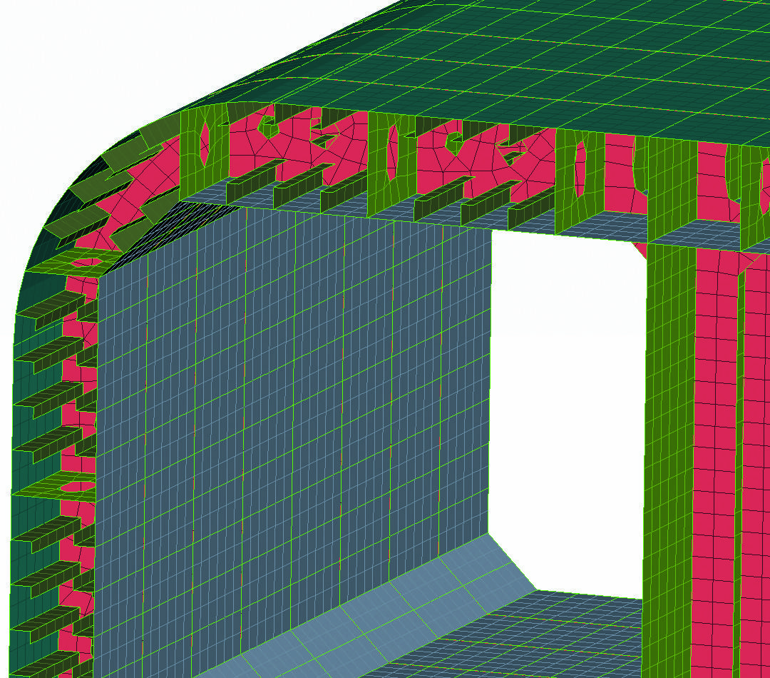
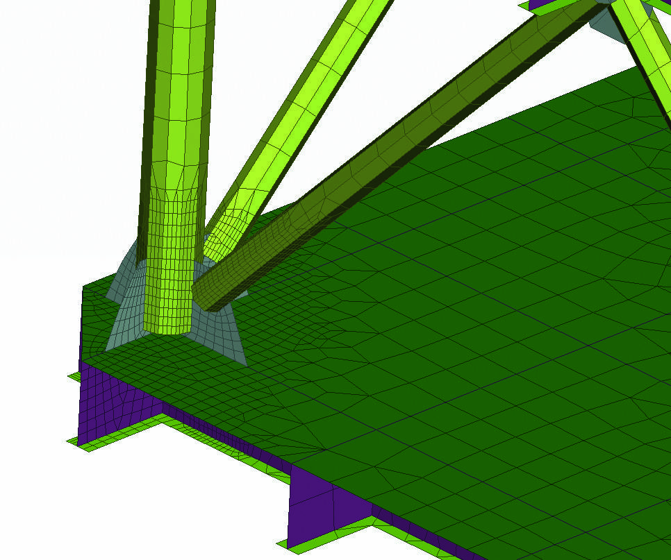
Another simplification action is the replacement of longitudinal stiffeners by beam elements. This action significantly reduces the number of small elements that represent the stiffeners. The beams applied have the same characteristics and behavior with the replaced stiffeners. Beams replacement is an automatic process in ANSA that is able to replace the whole model’s stiffeners with minimum interaction. Beams are offset and oriented to fit the stiffener position and also connected to the shells of the model (fig. 4).
2.3. Batch meshing
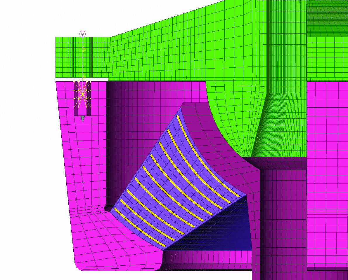
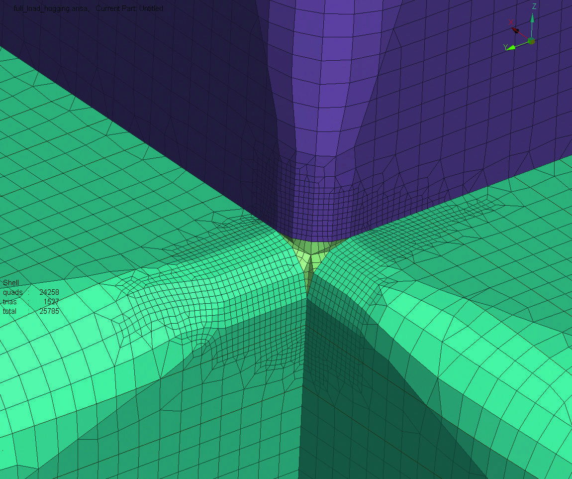
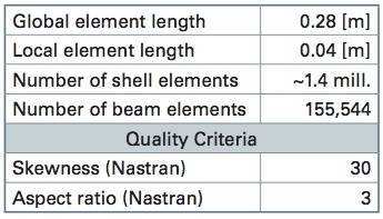
The meshing of the model is applied automatically through the ANSA Batch Meshing tool. Meshing parameters and quality criteria are defined for each sub-assembly. The whole meshing process is controlled by the Task Manager. Local refinement can also be applied on critical areas where accurate results should be extracted. A special meshing scenario can be defined for these areas as shown at fig. 5. The meshing information and quality criteria used for the platform are shown on table 1.
2.4. Loading condition
In this step of the model set-up, boundary conditions, loads and all auxiliary FE entities, such as additional mass, are applied. The non-structural mass applied represents the machinery on deck and hulls. This mass does not contribute to the model strength, so it is added as lumped masses distributed on the FE nodes. Another portion of mass will also be added in order to simulate the water ballast. The amount of water ballast is calculated to equalize the weight of fluids in storage tanks, and also the risers and mooring forces. The calculation tries to achieve a horizontal position for the platform. The ANSA Mass Balance tool is used for the calculation and distribution of the mass in order to achieve a prescribed mass value and COG position. The calculation process is controlled by the Task Manager sequence and runs automatically. The result is the application of different amounts of mass in every tank, distributed on their nodes (fig. 6).
The weight from mooring and raisers lines is applied as nodal forces on the deck. In order to avoid high stresses on single nodes, rigid elements distribute the forces on a wider FE area of the deck.
At the final step of the analysis definition, the platform is positioned on a 10 m height trochoidal wave. A special tool is used to balance the model on the wave by iteratively adjusting the draught and trim until the resultant net force and moment of the platform is ideally zero. The buoyancy force is calculated and applied on the model as PLOAD4 on the hull elements below waterline with a linear variation with the water depth (fig. 7). Using the balancing technique the model is able to run in »Nastran« solver without the need of displacement constraints (SPCs), which would lead to high local stresses. A Nastran keyword for inertia relief (INREL) is added for this solution.
2.5. Analysis results
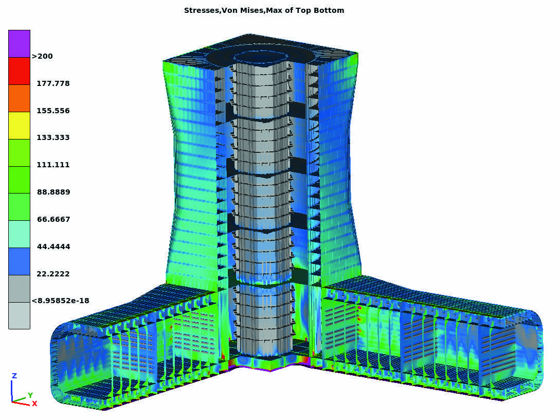
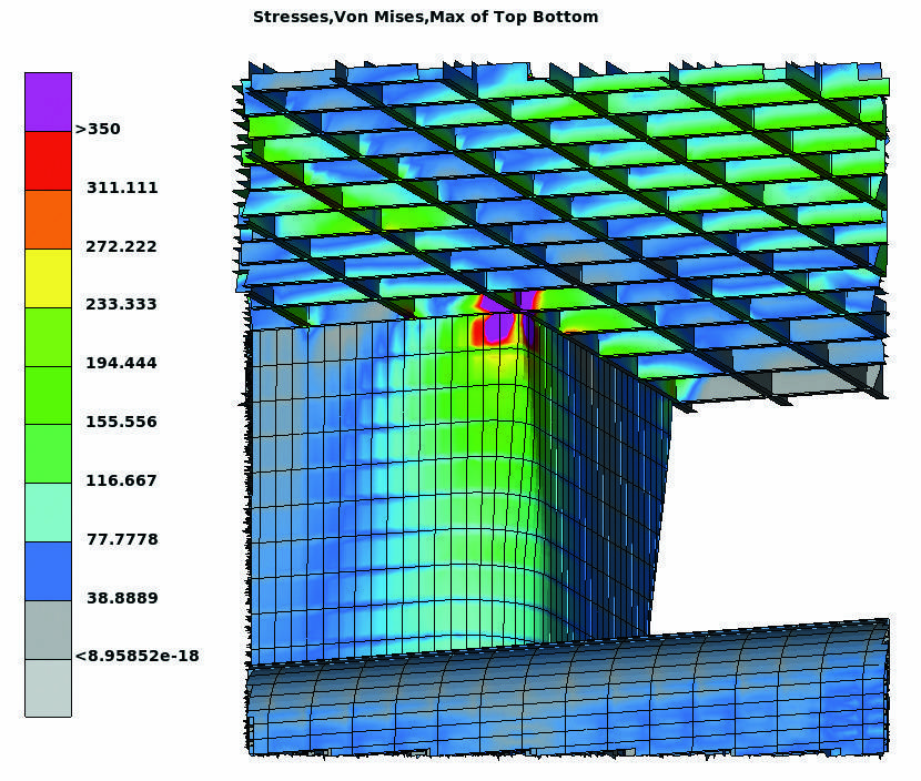
For this static analysis the Nastran solver has been used. The results of the analysis are presented and examined in ETA post-processor. Critical areas with high stress can be identified and further analysis can be done for every case. Some results are presented below (fig. 8).
3. CFD analysis of a wind turbine rotor
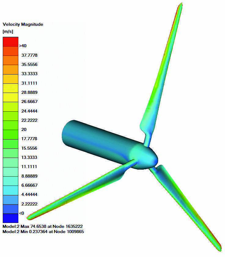
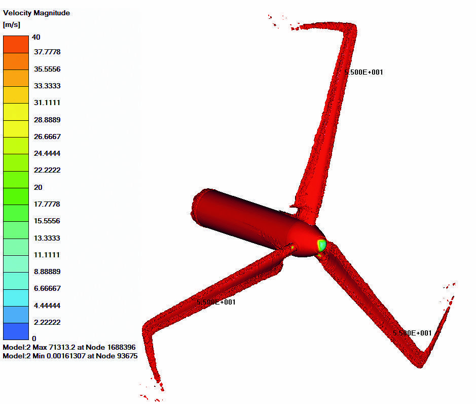
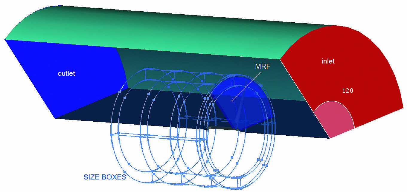
A CFD analysis of a wind turbine’s three bladed rotor is performed at the second case study (fig. 9). Since the model is axisymmetrical, the computational domain of this simulation consists of only one blade, the rotor hub, and the volume around the blade. Periodic boundary conditions are used to model the other two blades to the calculation.
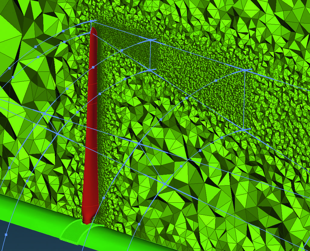
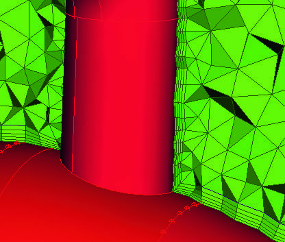
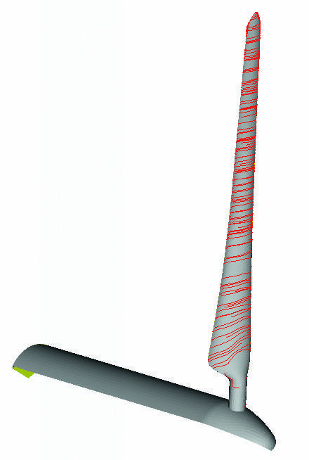
The blade geometry has been meshed with a variable size triangular surface mesh. In the fluid domain, additional refinement is applied on areas of interest with the aim of ANSA’s Size Boxes tool. The boundary layer, generated on the blade, consists of ten layers of prisms, generated in aspect mode with a growth factor of 1.2 and first height of 2 mm. A tetra mesh has been generated on fluid domains with a total size of nearly 24 million tetras and pentas. The whole meshing process of the blade and fluid domain is elaborated through the ANSA Batch Meshing Tool (Fig. 10).
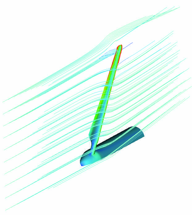
For this analysis the Ansys Fluent v14.0 software has been used. Converge was achieved after about 200 iterations and 2.5 calculation hours on a 12 CPUs machine. The results of the analysis are presented in ETA post-processor, which supports results from numerous CFD solvers. Some results, such as velocity and vorticity in contour plot, streamlines, and path lines of the flow, are shown on figures 11 to 14.
4. Structural analysis of a riser’s flexible joint
At the last case study, a flexible joint of a riser line is analyzed (fig. 15). This device connects a riser line to the platform. Since the riser and platform are continuously in motion, the flexible joint should be able to absorb relative movement between the connecting parts and avoid damage on the riser. To allow this movement, the flexible joint has two moving parts. The target of this example is to ensure that the moving parts will remain in contact, in any loading condition, avoiding any fluid leakage. A static analysis is performed using the Abaqus solver for two different loading conditions of the riser line. The model consists of two bodies (first and second body), a tube where the riser is welded and an elastomeric element. The semi spherical surfaces of the first body and tube allow for the rotation of the tube in order to absorb the riser’s motion. The elastomeric element applies pressure between the first body and the tube and keeps these parts in contact.
4.1. Model set-up
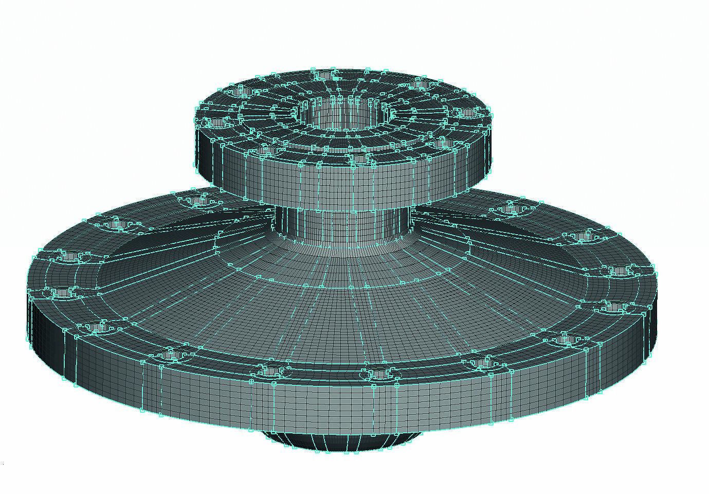
The flexible joint is meshed with full hexa mesh of approximately 200 thousands hexas. Each part of the model is meshed separately using different meshing parameters. In order to apply the 100 % hexa meshing, a special tool of ANSA is used, the Hexa Block tool. This is a semi-automatic process where hexahedral domains are defined and fit on the model’s shape. Then, hexa meshing is applied on these domains, which correspond to the mesh of the model. All parts that are meshed are axisymmetric so, only a few domains are defined and copied by rotation to cover the whole model. The mesh and Hexa Block domains of the first body are shown on fig. 16.
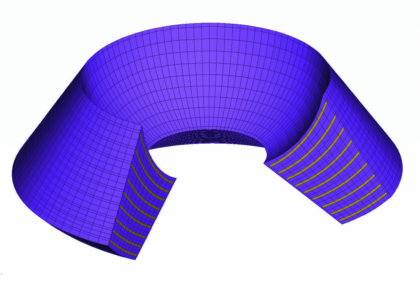
The elastomeric part is also meshed with hexa elements. Steel plates inside the elastomeric matrix reinforce the part (fig. 17). The connection between elastomeric and steel plates is done by pasted nodes.
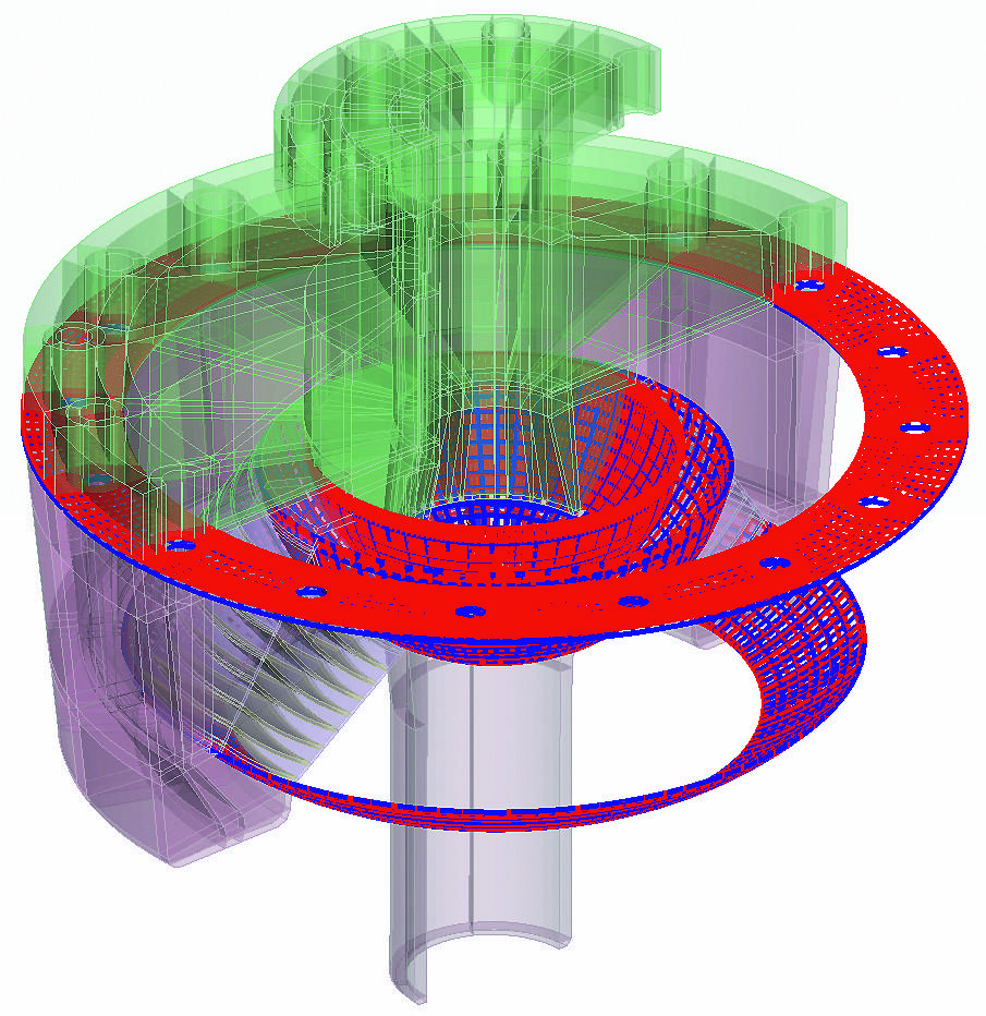
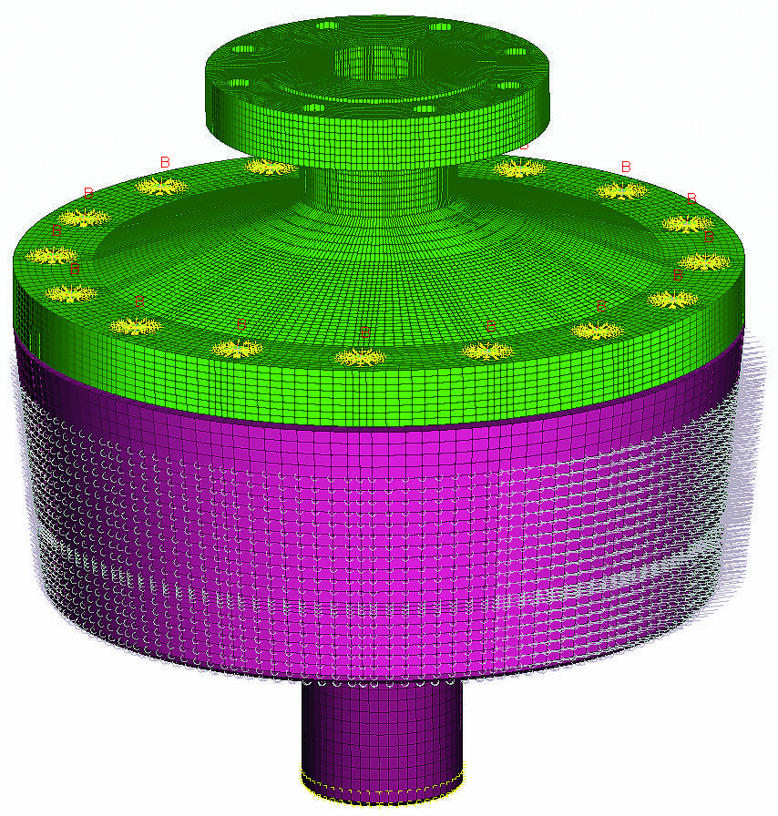
The next step of the model set-up is the definition of contacts between the parts of the assembly. Contact entities could be of »sliding« type, such as the contact between the first body and tube where sliding is allowed. In this case a friction model is applied with friction coefficient of 0.2. The rest of the contacts are of »tied« type, such as the contact between the elastomeric part and the tube due to the fact that the two parts are considered glued and no movement is allowed between them. Totally, four contact pairs are identified. The use of a special ANSA tool for this purpose facilitates the identification of the mating surfaces and the definition of the contacts. The user just needs to confirm the matting surfaces and select the type of the contact. All contacts are shown on fig. 18.
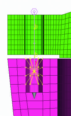
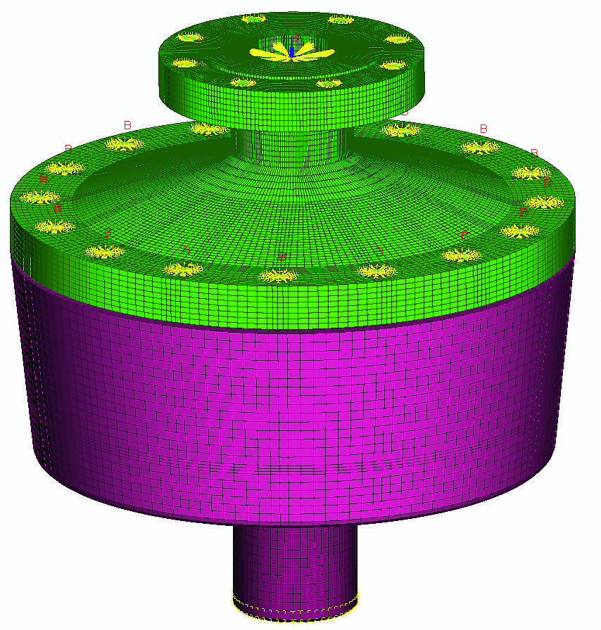
The first and second bodies are connected together using bolts. At the FE model, bolts are represented by a combination of beams and rigid bodies. The definition of the bolts FE representation is an automatic process in ANSA, which consists of two steps. Firstly, the bolt positions are identified by the bolts’ holes and the connecting parts, and ANSA Bolt Entities are applied at these positions. Then, at each Bolt Entity an FE representation is created according to the user specifications. In this analysis the bolt FE representation consists of Beams for the bolt body and rigid elements for the bolt head and thread (fig. 19). A pre-tension model is also applied on the bolts to simulate the tightening force.
The elastomeric part should apply pressure to the tube part by a pre-tension. In this case, squeezing the elastomeric part during the assembly process performs the pre-tension. The elastomeric part in its initial dimensions causes a small gap between the first and second part. During the simulation the bolts’ pre-tension closes the gap and squeezes the elastomeric part and so, the pressure on the semi-spherical surfaces is applied (fig. 20).
The first load case arises when the riser is welded on the flex joint and the latter is transferred from a crane (fig. 21). The crane hook is mounted on the upper flange of the flex joint. The flex joint should withstand the load of the riser while the semi-spherical surfaces should not be separated. Two opposite loads are applied which are connected to the assembly by rigid body elements. The second load case is when the flex joint is situated on the supporting frame of the platform and the riser applies load at a certain angle. In this case, SPCs are applied at the bottom and the sides of the second body to simulate the supporting frame constraint (fig. 22).
4.2. Analysis results
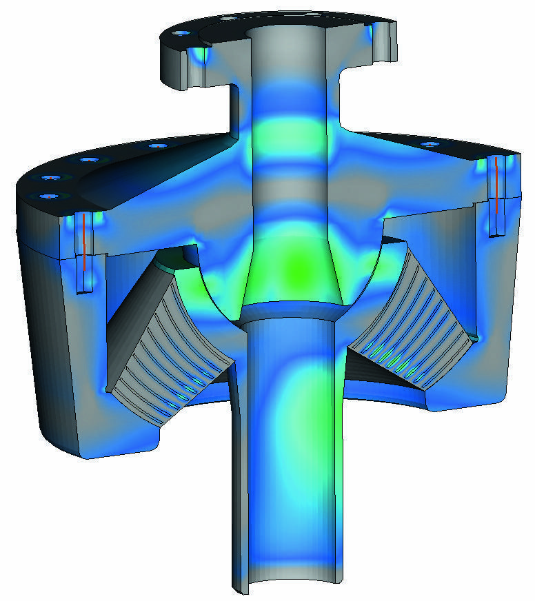
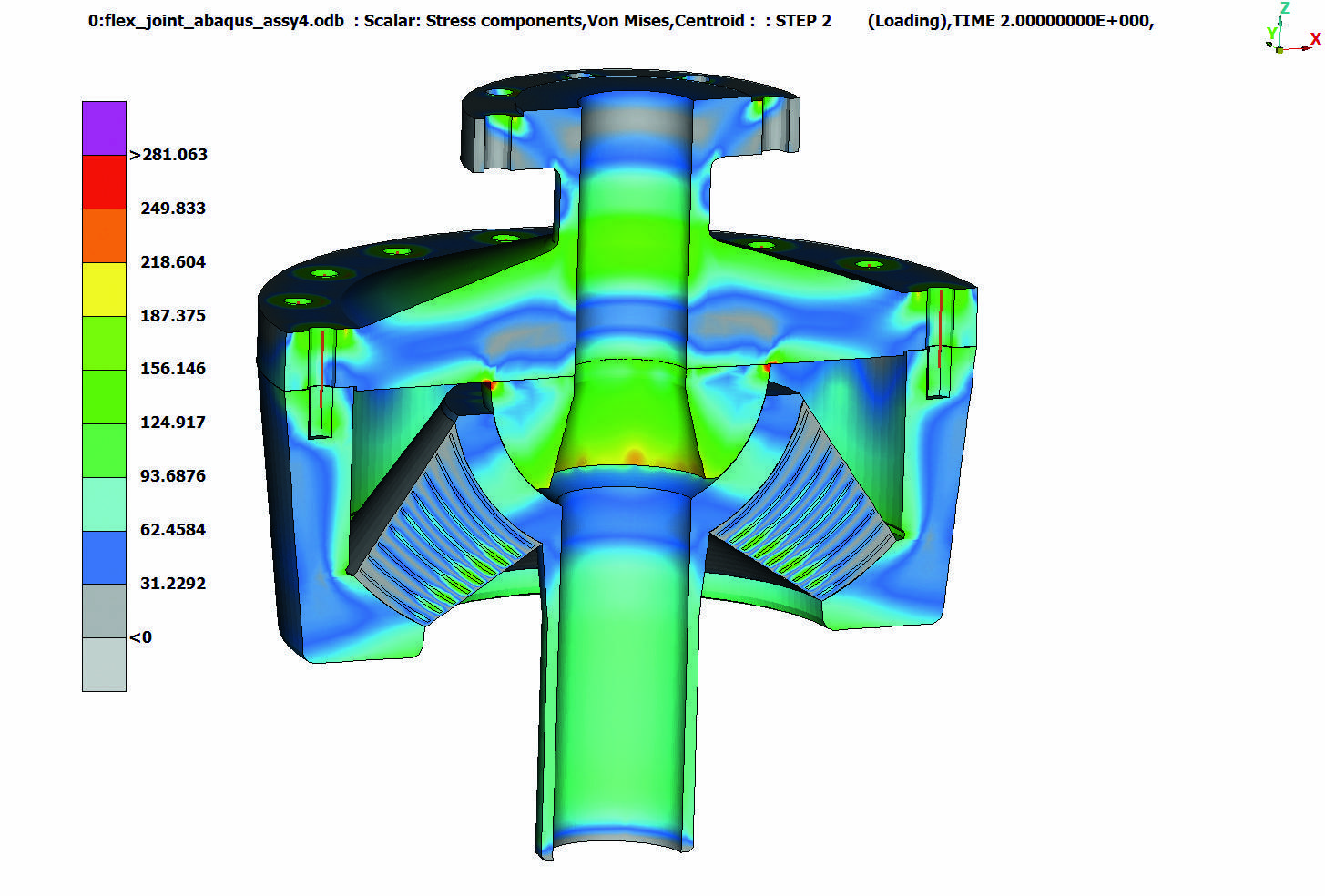
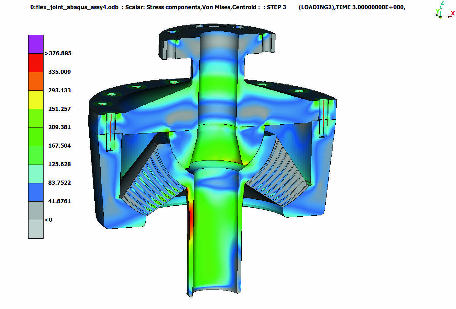
The model is solved with the Abaqus solver and the run lasted about 1 hour and 30 minutes in a four CPUs machine. The results are presented in ETA post-processor. At the first load case, the maximum Von Misses stresses appear on the first body on the edges of the semi-spherical surface. Significant stresses also develop on the connecting bolts since they carry both the riser and the pre-tension loads. In the second load case, the tube is subjected to high stress even if the tube is allowed to rotate on the semi-spherical surface. Results from ETA are shown on figures 23 and 24.
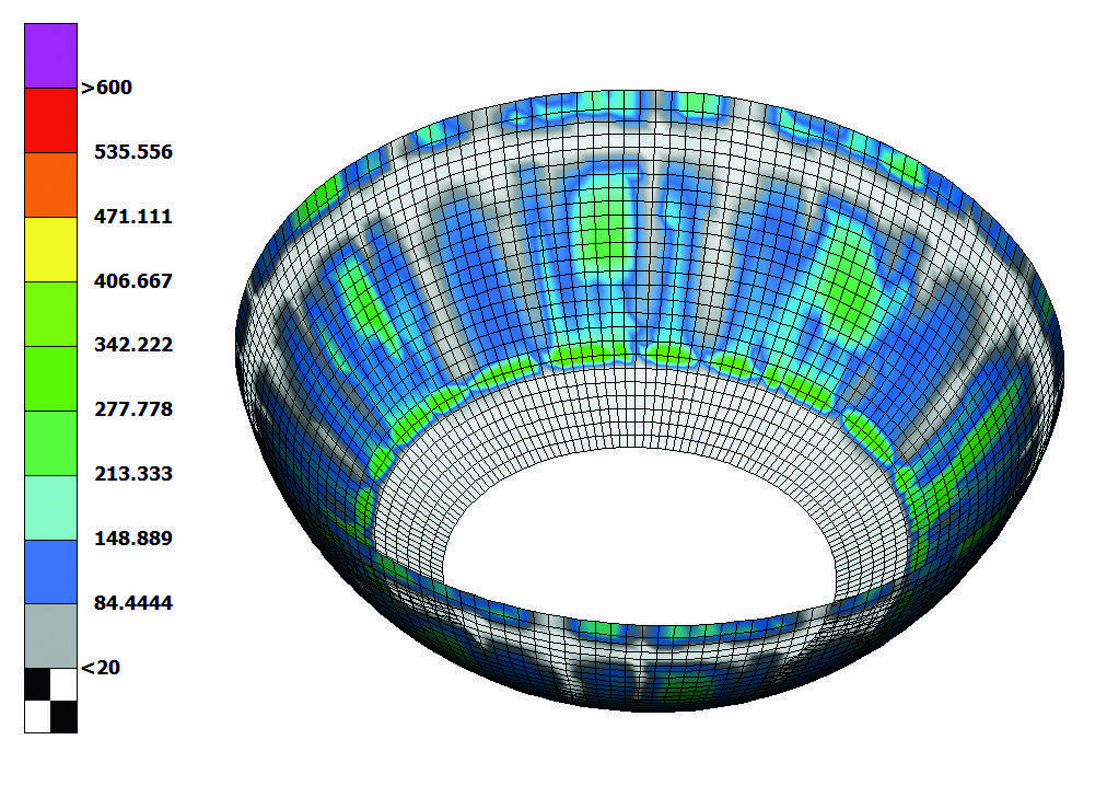
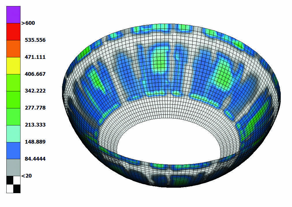
In order to investigate the contact pressure between the moving parts, a special ETA tool is used. This tool is able to create a shell element representation for the contact surfaces to facilitate the visualization of the pressure distribution. The contact pressure for the pre-tension first and second load case are shown on figures 25 to 27 respectively. There is no separation of the surfaces for all load cases. The uneven distribution of the pressure shown as a »radial stripes pattern« is dependent on the element length of the surface. Finer mesh at this area results in smoother pressure distribution and minimization of the »radial stripes pattern« effect.
5. Conclusions
ANSA pre-processor was successfully and efficiently used for the definition of several CAE analyses scenarios for structural and CFD disciplines. Process organization and standardization is possible using the Task Manager tool. The needs of CAE set-up for the offshore structures design are covered by special tools. Applications like wave creation, mass balance, vessel balance on waves, and buoyancy calculation can be automated using the above-mentioned tools. ETA post-processor is a versatile post-processor which provides sophisticated tools for results reporting and evaluating and it can cover the needs of the offshore industry with success.
Authors:
George Korbetis,
Dimitris Georgoulas,
both at BETA CAE Systems S.A.,
Thessaloniki / Greece,
ansa@beta-cae.gr
George Korbetis, Dimitris Georgoulas


