In order to optimize a vessel design’s carbon footprint, an engine with the lowest specific fuel oil consumption is desired. However, decisions that lead to the lowest SFOC are not always as clear-cut
Naval architects are experts in the process of optimizing the propulsive efficiency ηD of a vessel design, and thereby achieving[ds_preview] the lowest power requirement PD for a given vessel speed.
ηD = ηH x ηO x ηR
PD = PE : ηD = (RT x V) : ηD
where:
ηD: Propulsive efficiency
ηH: Hull efficiency
ηO: Open-water propeller efficiency
ηR: Relative rotative propeller efficiency
RT: Vessel-towing resistance
V: Vessel speed
PD: Propeller power requirement (delivered power)
Naval architects are also familiar with the impact that engine selection can have, and it is usually clear that the highest engine efficiency – and thereby lowest specific fuel oil consumption (SFOC) – is desired. However, decisions regarding the engine that lead to the lowest SFOC are not always as clear-cut.
A modern and holistic approach to vessel fuel-optimization is to apply the fuel equation. This expresses the power, in terms of the flow of the fuel’s heating value, that needs to be supplied to the main engine to maintain a given vessel speed.
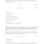
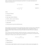
Pfuel = (RT x V) : (ηH x ηO x ηR x ηS x ηE)
where:
ηS: Shafting efficiency
ηE: Engine efficiency
For a two-stroke engine installation where the main engine is directly coupled to the propeller, the shafting efficiency can be taken as a fixed number that is usually in the range 0.98 to 0.99. However, determination of the overall efficiency effects of changes of the engine type and layout is not as straightforward and is the focus of this article.
The combustion engine’s basic job is to burn fuel in a small volume and subsequently expand the resulting, hot, high-pressure combustion gases to a larger volume, while delivering power to that part of the combustion chamber wall that provides the expansion – namely the piston. It should be understood that a high expansion ratio is important in order to achieve high engine efficiency. That is, the greater the extent that the hot gasses can be expanded and cooled before the exhaust valve is opened, accordingly the more energy can be extracted from the gases and the higher the engine efficiency and the colder the exhaust gas will be.
Derating
In principle, it would be ideal to burn the fuel in a volume so small that the hot, high-pressure combustion gasses could expand until the cylinder pressure reached atmospheric pressure before the exhaust valve was opened. This is not feasible for a number of reasons that are outside the scope of this article. However, it is relevant to mention that if such small combustion chambers were used, it would reduce the amount of oxygen in the chamber unless the pressure was very high – higher than possible from an engine-design point of view. Accordingly, a small combustion chamber means a reduced amount of oxygen, which itself means that it is not possible to burn as much fuel. The result is a lower engine torque and thereby lower power-output. Despite this, the chamber volume is often reduced to some extent – this is called derating. A derated, marine two-stroke engine has a combustion chamber that is smaller than a fully-rated version of the same engine type and this is done to increase the expansion ratio, and thereby the efficiency of the engine, at the expense of a lower power-output.
High maximum cylinder-pressure
In the previous explanation, it was assumed that all the fuel is burned when the cylinder volume is at its smallest, at the position in the engine cycle called TDC (Top Dead Centre). In terms of engine efficiency, it would also be beneficial to burn all the fuel at TDC.
In an engine in operation the fuel cannot all be delivered and burned at once. Even if possible, it would result in cylinder pressures that were too high. The fuel is therefore injected following a carefully designed injection profile. This gives a high engine efficiency and power output without exceeding the physical limits of the engine and other restraints such as exhaust-emission requirements. In order to better understand the positive effect on fuel consumption of an engine that can withstand a high maximum cylinder pressure, let’s take a look at the fuel-injection process:
• Early part of the fuel-injection profile: fuel is injected and burned near TDC and will expand and cool to the greatest possible extent before the exhaust valve is opened. The fuel energy released in this way is most efficiently converted to mechanical energy, which is delivered to the piston.
• Late part of the fuel injection profile: fuel is injected and burned after the piston has left TDC. The cylinder volume is larger at this time and the combustion gasses resulting from burning this portion of the fuel will not expand and cool to the same degree as earlier. The energy in this portion of the fuel is less efficiently converted to mechanical energy.
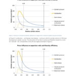
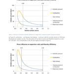
We want to inject and burn the fuel quickly to achieve the highest efficiency and power output. This is limited by the maximum cylinder pressure that the engine can withstand. Thus, it is important to have an engine that is designed for a high maximum cylinder pressure as can be seen in Figures 1 and 2. In Figure 1, combustion – and thereby heat release – continues until the cylinder volume is 0.28 times the maximum cylinder volume. The last portion of fuel that is burned can therefore expand by a ratio of 1.00/0.28 = 3.6. Compare this to the 200bar engine illustrated in Figure 2.
In Figure 2, the same amount of fuel has been injected as in Figure 1, but fuel injection and combustion can occur faster than in Figure 1 without exceeding the maximum-allowable engine cylinder pressure. Combustion and heat release finish at a cylinder volume of 0.22 times the maximum cylinder volume, which results in a higher expansion ratio of 1.00/0.22 = 4.5 for the last portion of fuel burned. This means that more of the chemical energy in the fuel is extracted as mechanical energy by the piston before the combustion gases are expelled to the exhaust, compared to the situation in Figure 1, resulting in higher engine efficiency.
Advances in engine design have made it possible to design marine two-stroke engines that are capable of withstanding maximum cylinder pressures of 200bar. This makes it possible to reach unprecedented engine efficiencies and lower SFOC. By derating it is possible to achieve even lower fuel consumption.
More on derating
The degree of derating can be identified by how much the maximum engine torque is reduced. Although it is possible to look at the torque values, it is more usual and typically easier to look at the so-called »mep« values that are independent of engine size (mep = mean effective pressure, work done per engine cycle per cubic meter of engine displacement Vd). Engine designers use mep instead of torque almost exclusively.
mep = Wcycle : Vd
mep is proportional to engine torque according to:
mep = (2 x π x Torque x X) : Vd (x = 1 for a 2-stroke engine, x = 2 for a 4-stroke engine, all values in SI units)
Derating an engine reduces maximum torque – equivalent to maximum mep – in order to create an engine with a lower fuel consumption. A high maximum cylinder-pressure also reduces fuel consumption. Combining the two concepts leads to the old rule that the ratio between maximum pressure and mep should be as high as possible to achieve the highest possible engine efficiency. Considering that a given engine type is designed to withstand a certain maximum pressure, the objective is to reduce mep if the focus is more on high engine efficiency than on high engine power.
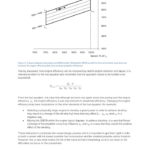
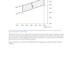
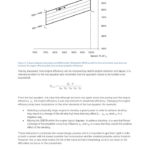
When ordering a marine two-stroke engine, the degree of derating can be seen by the position of the specified maximum continuous rating (SMCR) in the engine layout diagram (Figures 3 and 4). Referring to Figure 3, since a given power output from the engine is often required, derating is usually not achieved by reducing the SMCR power but rather by adding an extra cylinder to the engine. Thus, the layout diagram moves vertically upwards and, for a given position of the SMCR, this results in a lower mep and, thereby, derating. Figure 4 illustrates a movement of the SMCR within the engine layout diagram that will not result in derating.
Having discussed how engine efficiency can be improved by careful engine selection and layout, let’s return to the fuel equation and remember that the approach needs to be holistic to be successful. From the fuel equation it is clear that engine efficiency E is just one element of vessel fuel-efficiency. Changing engine efficiency may have implications on the other elements of the equation, e.g.:
Selecting a physically larger engine to develop a given power in order to achieve derating may result in a change of the aft-ship hull lines that may negatively affect RT, ηH, ηO and ηR.
Moving the SMCR within the engine layout diagram, to achieve derating, in a way that forces a change of the propeller curve may influence ηO and ηR in a way that may cancel the positive derating effect.
These interactions complicate the vessel-design process. It is important to get them right in order to build a vessel with the lowest possible fuel consumption and the smallest possible carbon footprint.
Kim Rene Hansen


