A crucial task for any ship design company is to install an appropriate amount of power into a vessel to achieve given operating speeds. This requires not only accurate hull resistance values but also a precise resolution of the propellers’ wakes. Furthermore, propeller-hull-rudder interactions largely impact the overall flow field and
should hence not be neglected.
present a possible solution
The controller implemented in FINE/Marine currently allows for three types of self-propulsion simultation, depending on the objectives of[ds_preview] the designer:
Type 1: The ship advancing speed is known but not the propeller rotational speed
Type 2: The propeller rotational speed is known but not the ship advancing speed
Type 3: The power of the shaft of the propeller is known but neither the ship advancing speed nor the propeller rotational speed.
Why would we need a dynamic controller for these calculations? If we have a look at the first type of self-propulsion, traditional approaches recommend for a given ship advancing speed to run at least 3 computations with different imposed propeller rotational speeds in order to predict the propeller revolution rate at which a ship achieves its self-propulsion point. Furthermore, the open water performance curve of the propeller is needed to estimate an initial rotational speed.
All these computations require a non-negligible amount of engineering and CPU time. Hence, would it be possible to compute the self-propulsion point at one shot and without even knowing the open water performance curve? With the dynamic controller in Numeca’s FINE/Marine, the answer is yes. The controller will read all the information from the solver in order to find the corresponding unknowns of the simulation. This is done dynamically during the computation without any engineer intervention.
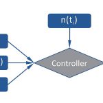
How does the dynamic controller work? The controller aims at ensuring that the algebraic sum of all the forces acting on the ship (including the propeller) goes to zero at the end of the computation through constantly adjusting the unknowns of the system during the simulation. The core function behind the controller is:
Where Fexternal is an external force applied onto the ship (like a towing force), Fship is ususally the hull drag and Fpropeller the propeller thrust. This equilibrium is formulated along the ship advancing direction. The controller estimates the propeller revolution rate n for the time step »i + 1« based on Fship and Fpropeller of the time step »i« and Fexternal. The same concept is applied for the simulation types 2 and 3. So only one computation is needed and it is subdivided into two main stages with the controller always active:
Stage 1: The ship is accelerated until reaching its target advancing speed. In practical terms it is comparable to a classical resistance computation, hence the time step can be large.
Stage 2: The time step is continuously reduced based on the estimation of »n« and the computation is run until Fship and
Fpropeller achieve an asymptotic value.
In practice, the user only needs to provide very simple data such as the propeller diameter, the ship advancing speed and Fexternal (if any). This makes the use of the controller very easy, general and valid for any configuration.
Case setup
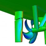
The present example is based on the case 2.3a of the CFD Workshop Tokyo 2005, the KCS model scale tanker validated/evaluated/investigated by the Maritime and Ocean Engineering Research Institute (MOERI). This simulation corresponds to type 1. Stage 1 and Stage 2 are performed successively during one single computation. The ship position is fixed and an external force
(Fexternal = 30.3 N) as used in the experiments is applied. At stage 1 the ship is accelerated to its maximum speed (2.196m/s) using a time step of 0.03 s. When forces and ship motion reach a nearly steady state, the time step is reduced from 0.03 s to 0.000526 s with a tangent hyperbolic law during ten propeller rotations.
Results
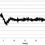
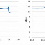
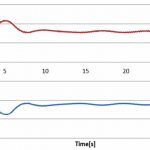
The efficiency and effectivity of the dynamic controller on the RPM are illustrated in the next figures. Fig. 2 shows that after the acceleration (t = 10 s) the force balance oscillates around zero. When the time step is reduced (t = 24 s) an abrupt transient appears due to the sudden variation of the propeller thrust, but the controller quickly lowers to oscillate around zero. At the end of the stage 2 the oscillation amplitude of is less than 1% of the final total vessel resistance Fship. Fig. 3 illustrates how the time step reduction during stage 2 allows the controller to predict n more accurately. The upper graph shows the evolution of n during the whole computation, whereas the bottom plot details only stage 2. After eleven propeller rotations n converges towards 9.56 rps which is only 0.6% larger than the experimental result (9.5 rps). Finally, Fig. 4 shows the time evolution of both, hull drag and propeller thrust, during the whole computation, indicating clearly the convergence of both quantities at the end of the stage 2.
Conclusions
The dynamic controller divides by a factor of almost 3 the number of time steps required to compute the self propulsion point compared to classic approaches. Furthermore, no open water computation is needed and only one computation has to be set up. In addition to the engineering and CPU time saving, the operating point is computed with higher accuracy than with the classical approach. In the case presented, a discrepancy of only half a percent for the propeller rotational speed was found. The main advantage of the dynamic solving approach is the gain in time, three times less pre-and-post-processing work including human time (and potential error) reduction. This is extremely important for the end user and also helps reduce the guesswork involved with the initial solutions of the traditional method.
Authors: Alvaro del Toro, Numeca International
alvaro.deltorollorens@numeca.be
Dr.-Ing. Thomas Hildebrandt, Numeca Ingenieurbüro
thomas.hildebrandt@numeca.de
Alvaro del Toro, Thomas Hildebrandt


