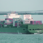
Already in the beginning of 2004 first drafts of a container vessel with a capacity between 4,000–5,000 TEU were discussed at Reederei Buss. From 2005 on several discussions were held with various yards in Europe and Asia. Very good cooperation experiences with the engineering office Neptun – Stahlkon-struk-tions GmbH and Chinese Zhejiang Ouhua shipyard in developing and completing another vessel type in the past led to the conclusion to take up this new challenge together again. Therefore, in 2006 a contract was signed between Reederei Buss and the private Chinese shipyard Zhejiang Ouhua on Zhoushan island to build four container vessels under the series name CV VENUS 5300.
This was a time when numerous shipping companies were steadily looking for convenient building locations mainly in East Asia to[ds_preview] acquire tailor-made ships for a steadily growing market. Considering stagnating or decreasing freight markets led to the opinion, that a highly sophisticated vessel would increase the competitiveness on the market. Consequently a contract was closed creating not only a big challenge for the Chinese shipbuilding industry but also for the German design consortia as well as for the Germanischer Lloyd.
On a joint effort basis the concept of the ultimate Panmax vessel was developed between Reederei Buss via its newbuilding department, GB Shipping & Chartering and the design Consortium around Neptun Stahlkonstruktions GmbH. Within 18 months the design consortium leader Neptun – Stahlkonstruktions GmbH and its main partners NE (Rostock), WIG (Wismar) and Imtech worked out a detailed Tribon 3D-model enabling the Tribon – linked yard to build such a 294 m long vessel in a 15-months construction period without any remarkable information loss.
The first delivery took place in June 2009 with the vessel »CSAV Rio de Janeiro« (ex »Choapa Trader«) and the second unit was delivered as »CSAV Suape« (ex »Sonche Trader«) two months later. »Amazonas Trader« has been delivered in January and »Vargas Trader« will follow in April 2010. For all four VENUS type vessels charters had already been fixed in 2008 with well known charterers CSAV.
The following short description presents some main facts to illustrate how challenging it was for all partners to design and construct such a highly sophisticated container vessel with technical features high above ordinary state-of-the-art standards.
Ship’s compartmentation
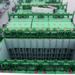
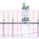
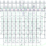
The arrangement of the deckshouse / fuel tank amidships more than approx. 100 m away from the engine room / funnel partition is quite unusual for traditional Panmax vessels and creates an advantage for the IMO and Panama visibility line. This leads to a new record for panmax vessels with 5,300 TEU, but also for concentrated, thus heating-up optimized fuel storage block, which is double-hull protected against the side shell. Looking at the longitudinal frame distribution gives the impression that not a single centimeter spare has been left between the pay load.
From the seven-tier accommodation house the crew can reach the passage ways under deck by a passenger Lift (Lutz) to walk to the engine room or to the reefer maintenance platforms in the seven cargo holds. There are two passage ways below main deck alongside the ship, interrupted by two bulkhead doors only. All cargo holds have a uniform double-40’ length.
Steel structure
The idea of a double hull / fuel tank centre was not new but needed rethinking in order to determine the most efficient steel structure. This had to be done in close co-operation with the classification society GL to take advantage from the better torsional stiffness and bending obstruction alongside the cargo area. As a result the ship is designed to achieve a lifespan of nearly twenty-five years in conjunction with a very low steel weight.
Special focus was drawn on the main deck and coaming bench radii in vicinity of the deckhouse to ensure the necessary resistance against fatigue. Coaming benches with a plate thickness up to 70 mm made from 390 kN/mm² HTS TM steel really challenged the yard and required extra training of welders as well as pre-warming and big x-ray checking efforts.
A high degree of jump loads had been specified to enable adequate flexibility during loading / unloading but also different load variations at sea. This was ensured by granted 3,000 MNm still water hogging moment at sea and 6,140 MNm in port.
The requirement to maximize the number of reefer container slots under deck was another issue. This was achieved by a special transversal open box girder design to reach six of the seven possible high-cube tiers with air and electrical energy supply and maintenance platforms.
Outfitting
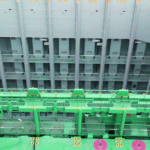
The ship is equipped with lashing bridges designed by Cargotec, which allow 120 t cargo for 40’ containers and in conjunction with lashing corridors 90 t for 20’ container stacks. The lashing bridges are moreover suitable for forming direct resting areas for 45’ containers, for easy reefer container maintenance, power supply and for lashing. But also to store the lashing material in most convenient positions.
To sort out all of these requirements and to assure the proper functionality we fixed already in the building contract with the yard and in the contract with Cargotec the early erection of a mock-up lashing bridge segment. This mock-up was observed nearly one year before the actual fabrication of the bridges and resulted in numerous modifications which could be considered in the design.
Accommodation
The ship has 30 cabins with own sanitary units and can accomodate four passengers, if indicated. Also cabins for apprentices are foreseen to cope with the need for well skilled crew in the future.
The ship is certified with a letter of compliance of the German See Berufsgenossenschaft (SBG). According to SBG rules, a spacious indoor pool is installed, which is properly insulated against the surrounding fuel tanks. The sauna next to the pool and the shower with chilled water supply completes this part of the crew’s recreation area.
Propulsion
Facing the most common propulsion philosophy in the pre-contract period, a bigger container ship, especially with a huge amount of reefer slots, was obliged to run fast, meaning 24–25 knots service. The use oft the surplus thermal energy became more and more popular and the intention to specify an exhaust gas power turbine to gain the promised 1,000 kW for electric consumers only failed by a missing interlink between main engine turbocharger (ABB) bypass and power turbine inlet (MAN).
Finally the 8th cylinder of the ME was replaced by a combined Shaft-Generator/Motor (SGM) configuration, to make the power management more flexible. Furthermore we switched to a delta-tuned common rail engine of type 7RT-flex 96C from Wärtsilä to take advantage of the anticipated better slow steaming capabilities.
Today, watching the first months of the two running ships one can conclude that both ships rarely need more than 45 % MCR to sail at the determined 19 knots This leads to a reduction of its prospected fuel consumption by nearly 50 %. Thus the vessel does not have a surplus of usable thermal energy which would be needed to drive an exhaust gas turbine. But certainly the PTO is being used frequently.
This means a ship pool running with 19 kn compared to possible 25 kn requires four instead of three ships for the same number of ton miles but consumes one third less fuel at all. This example reflects very well the present change in the shipping industry. A service speed of 25 kn on design draught, defined at 90 % MCR of ME, 100 % MCR of PTI, 15 % Sea Margin was achieved by numerous tests at HSVA by testing three different model propellers, three rudder bulb variations and some line modifications.
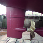
As a result of these tests we selected a 5-bladed high screw propeller (Wärtsilä CME) in combination with a large propeller cap, working close to a spacious rudder bulb, which is connected to a high efficiency twisted leading edge Becker rudder. The rpm. of the Propeller is restricted to 20 as lower limit for a continuous operation. This is not caused by the Common Rail Main engine – which would allow 10 rpm – but by the stern tube aft bearing, since it is necessary to keep the bearing temperature in a stabile balance.
Vibration impact on the deckshouse is marginal due to the distance between engine room and deckshouse.
As soon as the ME has developed approx. 10 % MCR while leaving a port, the SGM, used as motor can start to accelerate the ship respectively release the ME from rapid thermal load increase. From 95 rpm the SGM can increase the ship’s speed for approx. one knot, feeding the propeller with up to 4,000 additional kW.
In a first résumé it can be stated that so far the originally planned 8th cylinder of the ME has not been missed.
Variable fuel concept
The world faces significant changes in fulfilling the requirements of MARPOL VI, namely its revision by MEPC.176(58) in rapid limitation of NOx by means of Tier III from 2016 on and also extreme restriction of SOx at 0.1 % m/m S in European ports from 2010 on, Californian waters from 2012 on and all ECA (incl. SECA) waters from 2015 on, not to mention the unclear situation of the Particulate matters (PM). The importance of this fact will grow substantially with the planned enlargement of the ECA regions by nearly complete North-American waters within a 200 sm zone, approved by MEPC 59/24 July 2009 and pending for adoption at MEPC 60 in March 2010, coming into force July 2010.
Considering the above, one has to think of three different sorts of fuel which might be HFO with 3.5 % m/m S, low Sulphur HFO with 1.0 % m/m S and Low Sulphur Destillate Oil (LSDO) with 0.1 % m/m S in order to cope with all environmental aspects for the years to come.
The ship has therefore a three-fuel configuration and can handle different types of fuel very flexibly. Nevertheless the master needs to have a dedicated fuel management plan to provide the right fuel with the right temperature in sufficient amount at the right time.
All this requires experience and may lead the shipping industry to think about serious introduction of dual fuel ships which can burn natural gas, HFO and LSDO (as pilot fuel) with the advantageous side effects to reach Tier III (NOx) and to save 20 % of CO2.
Retrofit measures enabling main engines and GenSets to work with natural gas may become more popular. This, however, needs much more contribution from the engine manu-
wfacturers. Alternative scuppers or catalytic facilities may also move into the spot light.
Power supply
The RCP-certified reefer capability required a tremendous power plant, consisting of three MAN GenSets 9L32/40 and one 8L32/40 CR, developing a power of 16,895 kWel. The Common Rail engine was selected to enable a very low speed below 30 % MCR during port stays without any smoke emission and with low fuel consumption even at this stage. Used as a generator with max. 3,000 kW the SGM provides the normal ship’s load and power for some reefer containers whilst at sea.
The SGM (VEM) is frequency controlled by a Simar Drive Synchro converter (Siemens) with separate cooling unit and embraces an isolating transformer, a synchronous condenser machine and some other facilities.
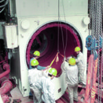
Sixteen copper poles, each weighing 1,000 kg, had been mounted on a specially shaped intermediate shaft. Then the 35 ton stator was shifted on sliding foundations in its final position, leaving an air gap of 7 mm around it. Already at 48 rpm (abt. 10 % MCR) of the ME the SGM can be engaged to deliver 1,500 kW power and from 80 rpm (abt. 60 % MCR on it reaches its full capacity.
Shore Connection
To cope with the Cold Ironing in California we thought about installation of shore supply facilities, but abandoned the idea due to the missing space and the heavy cost this would have caused. Today, this issue gets more and more important but may need a more global view in respect of the anticipated huge enlargement of ECA regions in the near future.
The ship is therefore equipped with a low and medium voltage cable connection only, thus waiting either for port-based development of transformers with self-adjusting frequency and voltage abilities or gas oil based own provision meeting the ECA requirements.
Power management
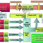
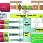
The flexibility of the power management can be shown by the examples given in the graphs below.
Reefer containers
The ship provides 1,200 sockets for the transport of 20’ or 40’ reefer containers, 1,025 slots of it are classified according the RCP (Reefer Container program) class mark of GL. The RCP certificate is still pending for the other 175 reefer locations as long as temperature check during a voyage with full reefer load on deck with three tiers has been proven.
RCP distinguishes between chilled reefer containers and frozen ones and determines the necessary power supply (in this case 7.2 kW per reefer). Furthermore RCP requires galvanically isolated power supply, a redundant GenSet (but not the SGM), specified air supply (4,500 m³ per hour and reefer) for the 543 reefer places in holds and free access to all refrigeration aggregates of the integral reefer containers. This means that all transversal walkways in holds are provided with platforms that are able to tilt, pluggable railings and transport routes to exchange defect reefer aggregates in order to cope with a different stowing pattern of normal or high-cube containers.
The heavy duty ventilation ducts are equipped with rounded edges and are painted with an abrasive resistant paint. They supply fresh air to the the reefer condensers by adjustable flaps. Their openings can be preset to distribute the air evenly between the six reefer slots of each duct.
Well in advance of finalizing the design of the ducts with a total length of 2,000 m and 900 supply openings, we erected a Mock-up duct at yard’s site with 20 m length on a horizontal testbed.
The intended fan and the fire damper in front were connected and tested. The calculated back pressure of the cargo hold was simulated and the velocity and flow distribution measured. The recorded values resulted in modified fans with higher efficiency of the impellers.
Intensive measurements had been executed by the turnkey supplier Heinen & Hopman in presence of the GL to check the proper running of all 104 fans (Witt&Sohn) and the measurement of the air velocities directly at the supply openings, but also at the exhaust air ventilators, mounted alongside the hatch covers by Cargotec. To simulate heavy weather condition one side of the hatches had been closed to check the sustainability of the air flow.
For electrical energy supply a medium voltage system with 6,600 kV was introduced to limit the short circuit currencies. Imtech installed five ring main units which feed 14 reefer transformers to transport the electrical energy via medium voltage near to the consumers. The transformers are therefore located in seven air-conditioned rooms close to the reefer distribution boards each.
Chiller System
Heinen & Hopman was the turnkey supplier for the whole HVAC system. After long discussion it was decided to install a double circuit chilled water system which distributes chilled water with 6 °C and 20 °C to the consumers. The 6 °C circuit provides the accommodation AC plant, the provision refrigeration plant, the galley and some workshops, whereas the 20 °C circuit feeds the fancoil units in all ten transformer rooms and both switchboard cabinets.
The water / glycol-chilled fluid is cooled by a 700 kW chiller unit using R134a by two Bitzer screw compressors.
At the consumer side fancoil units circulate the ambient air through chilled water / air heat exchangers to keep the temperatures in the room below 45 °C.
Ballast water handling
Especially in these days, when Container ships are not always travelling on summer load line, quick ballast water handling in ports becomes more important due to the very fluctuating load conditions.
Additionally the ballast water exchange procedure requires a flexible and automatic procedure. The ship is equipped with a Pleiger Tank Management System which delivers all data to the integrated Kongsberg automation system. From the workstations in the Engine Control room the ship’s office or the bridge, the tank handling can be controlled or monitored.
Various mimic diagrams allow interactive handling of the tanks and attract automatic functions like source-target transfer or presets of a flow-trough or sequential exchange sequence. The system works automatically during the exchange in handling the pumps and valves and registering the changed amount of all preset tanks.
A frequency converter controls one of the two 800 m³/h BW pumps or half the capacity of both in order to keep a pressure / suction equilibrium during the flow-through exchange. An ejector transports the residual amount of BW, if indicated by the loading pattern.
The ship is provided with place, pipe and cable connection for later installment of a BW treatment plant, probably required from up 2016. The real application of such a plant needs accurate planning in advance. Questions have to be solved before, like determining the right pump capacity (800 m³ per hour is far beyond any feasibility), considering a second pipe system with smaller diameters, thinking on increased fresh water production, replacing steady sea water etc.
Special features
KYMA – shaft power meters
The shaftline is equipped with two KYMA strength gauges, one between ME and SGM and one between SGM and propeller. The sensors measure the torque values, calculate the shaft power and deliver the values to a display unit in the navigation console of the bridge. Here, the navigator can observe the shaft power in real time, depending on weather conditions but also on trim and draught variations. The trim at least can be varied by ballast transfer to find the most economical floating position.
The values for actual fuel consumption, ship’s electric load and SGM’s supply / consumption are also displayed at the KYMA display.
InexMan
The Interschalt / Seacos Loading PC and Pleiger worked out an interlink between the heeling control system and the loading computer to execute 10 minute-inclination tests directly in port or shortly after leaving. This GL-certified system enables the master to assure about the ship’s true stability, compensating any underestimation of the gravity centre of the recently loaded containers.
Separate bunker stations
The HFO tanks are far away from the MDO, lub oil and sludge tanks. Therefore, also the bunker stations have been split to enable separate transfer with bunker boats if suitable.
Environmental passport
The ship is classified with an Environmental Passport. This requires facilities for evacuating and exchanging Freon refrigerants and immediate gas detection, provided by Heinen & Hopman.
High Pressure Deckwash system
The ship has a high-pressure deckwash system with a connection alongside the walkways to clean areas under high pressure.
Double-ICCP system and antifouling systems
A split ICCP (Impressed Circuit Current Protection) – system to cover the ship’s hull incl. propeller and rudder is installed with the monitoring device in the engine room. The sea water filters and the bow thruster tunnel have separate impressed antifouling systems from Cathelco.
IAS – Integrated Automation System (Kongsberg)
Four workstations in ECR (2), ship’s office and bridge allow comprehensive activities to control and monitor the PMS (Power Management System), the pumps in ER, the Tank Management of Ballast and Fuel, the control of the Bilge system, cargo hold fan assembly, engine room fans, passage way fans and circuit breakers for the ring main units for reefer supply. The monitoring function embraces all alarm indications, safety systems of engines, fire damper and bulkhead door indications etc.
Sterntube Sealing System
A Wärtsilä CME Airguard 3AS 950 aft sealing system with three Viton lip rings protects the environment safely against oil outflow or water ingress. The fwd. sealing systems is provided by MK-II 950 type with two Viton lip rings.
Bow Thruster
A 2,000 kW Bow Thruster (Wärsilä) is installed with a medium voltage motor, driving a hydraulically controlled pitch propeller. The motor is sea-water cooled and has emergency abilities in air-cooled mode for a certain load.
Torsional Vibration Damper
An eight tons weighing Torsional Vibration Damper (Geislinger) of type D 240/7 is mounted at the fore front of the ME with a display to monitor the behavior of the damper in the ECR.
Cylinder Pressure Indication System
A Cylmate pressure indication system with a monitoring display in ECR is installed to observe the cylinder pressures and to detect misfiring or leakage problems immediately.
Resume
The challenge was settled by the Neptun Design consortium working closely with GL and Reederei Buss, but also directly with the HSVA, other engineering offices and the turnkey suppliers of the main components, mostly located in Europe.
The yard sent their design experts temporarily to Neptun for familiarization with the Tribon model. Then the Tribon model was fine-tuned in China, implementing small pipes below 32 mm diameter and secondary cable routes as well.
After having started the production, a really high standard of pre-outfitting could be achieved to shorten the valuable dry-docking period.
The VENUS series has been and is being built with a remarkable amount of European contribution in form of design work and core production. The question is how long this can remain. Container ships or even all freighters will disappear from the orderbooks of the domestic shipyards, but the degree of design and component participation for ship deliveries in Asia should be kept as high as possible. Only with a certain basic work load, ensured by high – standard freighters for delivery abroad the innovative development and research in view of more specialized ships can be ensured.
Helge Sell


