1 Holistic ship design optimization
Ship design was in the past more an art than a science, highly[ds_preview] dependent on experienced naval architects, with good background in various fundamental and specialized scientific and engineering subjects. The design space was practically explored using heuristic methods, i.e. methods derived from knowledge gained through a process of trial and error, often over the course of decades. Inherently coupled with the design process is design optimization, namely the selection of the best solution out of many feasible ones based on one or several criteria. A systemic approach to ship design may consider the ship as a complex system integrating a variety of subsystems and their components, all serving well-defined ship functions, Levander (2003). Additionally, ship design should address the whole life-cycle, from design through operation to disposal.
The optimal ship in this respect is the outcome of a holistic optimization of the entire ship system for its life-cycle. Mathematically, every constituent of the ship’s life-cycle system itself forms a complex non-linear optimization problem. Even the simplest component of the ship design process, namely the initial conceptual design, is too complex for practice. Also, inherent to ship design optimization are the conflicting requirements resulting from the design constraints and optimization criteria (objective functions), reflecting the interests of the various stake holders: ship owners, ship builders, classification societies, administrations, insurers, cargo owners, etc.
Assuming a specific set of requirements (usually the shipowner’s requirements for merchant ships or the mission statement for government / naval ships), a ship needs to be optimized for cost effectiveness, for highest operational efficiency or lowest Required Freight Rate (RFR), for highest safety and comfort of passengers / crew, for satisfactory protection of cargo and the ship herself as hardware and, last but not least, for minimum environmental impact (accidental oil outflow, engine emissions etc.). Many of these requirements are conflicting and a decision regarding the optimal ship design needs to be rationally made.
In reality, even the specification of a set of design requirements with respect to ship type, cargo capacity, speed, range, etc. is complex enough to require another optimization procedure that satisfactorily considers the interests of all stakeholders of the ship as an industrial product and service vehicle of international markets or others. Actually, the initial set of ship design requirements is the outcome of a compromise of intensive discussions between highly experienced decision makers, mainly on the ship design and shipbuilding side, and end-users who attempt to articulate their desires and acceptable tradeoffs. A way to undertake and consolidate this kind of discussion in a rational way has been advanced by Brett et al. (2009).
Since the middle 1960s, with the advance of computer hardware and software more and more parts of the design process have been taken over by computers, particularly the heavy calculatory and drafting elements of ship design. Simultaneously, the first computer-aided preliminary design (CAD) software systems were introduced, dealing with the mathematical parametric exploration of the design space on the basis of empirical / simplified ship models for specific ship types or the optimization of design variables for specific economic criteria by gradient-based search techniques, Murphy et al. (1965), Nowacki et al. (1970). Computer-aided studies on the optimization of ship hulls for resistance and seakeeping or ship structural designs have matured over the decades, e.g. Papanikolaou et al. (1996), Valdenazzi et al. (2003), Zalek et al. (2006).
Progress in computing power along with the advances in software tools have provided the ship designer with unprecedented computation power and capabilities, permitting the realization of theholistic approach. Thus, today the designer can address and optimize multiple aspects of the ship’s life, at least the stages of design, construction and operation. General frameworks like »Design for X«, Papanikolaou et al. (2009c), namely »design for safety« and »risk-based design«, www.safedor.org, Papanikolaou (2009a), »design for efficiency«, »design for production«, »design for operation«, etc., indicate the trend to address ship design optimization holistically, Papanikolaou (2009b).
Genetic Algorithms (GAs), combined with gradient-based search techniques in micro-scale exploration and utility functions for the design evaluation, are advanced in the present paper as an effective optimization technique for large-scale, nonlinear design spaces and multiple evaluation criteria. Several applications of this approach may be found in the listed references, Abt and Harries (2007).
For the general concept and details of multi-objective optimization, see Birk and Harries (203) and Sen and Yang (1998). Comprehensive state of the art reports on modern ship design methods and computer-aided design procedures were presented by Andrews et al. (2009) and Nowacki (2009).
2 The generic design optimization problem
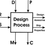
Following Nowacki (2009): »Design in engineering is a decision-making process that leads from a set of given product requirements to a product definition with all salient features for design assessment and production.« Fig. 1 shows the main elements of a design problem:
• R represents the requirements, e.g. the functional requirements for desired performance, the regulatory and legal requirements, regulatory and safety constraints, owner’s and user’s demands, operational scenarios and constraints.
• S stands for the solution space, i.e. a delimitation of the domain in which solutions shall besought with ranges of variation in concepts and design variables.
• D is the set of design variables, i.e. free variables under the designer’s control (e.g. principal dimensions).
• P stands for the parameters, which are variables not under the designer’s control, but dictated by the specific case scenario, hence not known in advance, e.g. route, range, cargo availability, port water depth, etc.
• M stands for the measures of merit, e.g. economic criterion.
• C are constraints, equalities and inequalities concerning stability, freeboard, capacities, etc.
The output on the right hand side in Fig. 1 includes the »Design Assessment«, where a proposed solution meeting all requirements is assessed, and the »Ship Properties« representing an enumeration of the achieved design properties, furnishing a complete product description and serving as a basis for production.
3 Parametric design of RoPax vessels
The methodology for the parametric design of RoPax vessels has been developed within the commercial ship design software NAPA. The vessel’s hull form and internal layout are generated automatically by NAPA macros. Additional macros or external software tools have been developed and linked to the design application for the assessment of the technical and economic performance of each design. The developed procedure can be executed on a step by step basis under the control of the user or in batch mode, once a set of design parameters has been assigned with the required values. The basic tasks of the developed methodology are discussed in the following.
3.1 Hull form development
The first step of the parametric design procedure is the development of the hull form. A set of NAPA macros have been developed, facilitating the fully automatic hullform definition. Considerable attention has been paid to ensure that the hullforms are of adequately high quality, to serve as the basis of the subsequent tasks, particularly the hydrodynamic and the intact and damaged stability calculations.
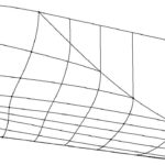
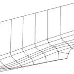
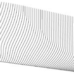
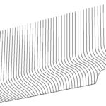
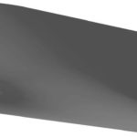
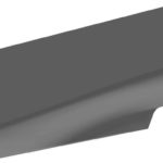
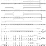
The hull is divided in three parts: entrance, run and parallel mid-body. The length of mid-body is often very small, as usual in fast RoPax vessels. The development of each part of the hull is based on a set of relevant design variables. First, the vessel’s main particulars are defined (length between perpendiculars Lpp, beam B, draught T), followed by the run and mid-body lengths, the freeboard, the vehicles deck height, etc. Additional parameters are introduced to control local hull form details, such as the size and shape of the bulbous bow (either conventional or goose-neck type), the shape of the flat of side and of the flat of bottom, the immersion of the transom, or the existence of a propeller tunnel, a duck tail or a stern wedge. Based on these parameters, three grids of definition curves are created defining the vessel’s entrance, mid-body and run. The resulting hull forms are typical of modern twin-screw RoPax vessels with fine fore-bodies and buttock-flow sterns, Fig. 2.
3.2 Resistance and powering calculations
Following the definition of the hullform, the geometric definition module is temporarily interrupted and the procedure continues with the preliminary resistance and powering calculations. This is because the required propulsion power determines the required length (and allocated space) of the Main Engine Room. The prediction of the vessel’s resistance may be performed by two alternative procedures:
1. The total calm-water resistance coefficient is decomposed as follows:
CT = (1 + k) CF + CW (1)
The frictional resistance coefficient CF is calculated by the ITTC 1957 formula. The wave resistance coefficient CW is calculated employing some potential flow theory method, e.g. SHIPFLOW, Larsson et al. (1990) or in-house tools, Papanikolaou et al. (1996). The form factor k, unless user supplied, follows a semi-empirical default value.
2. Semi-empirical regression formulae estimate the total calm-water resistance. The user may select the prediction method of Holtrop, as embedded in NAPA, or a semi-empirical method for conventional RoPax vessels. This latter method was derived by regression analysis of RoPax data from model tests carried out at NTUA in the last ten years. Here the resistance is given by:
RT = ( + ) · · Fn2 (2)
= -265.28 + 1758.1 · Fn – 2899.5 · Fn2 (3)
= 2322.7 – 14936 · Fn + 24852 · Fn2 (4)
is the displacement of the ship, Fn the Froude number and = L/ 1/3 is the slenderness ratio. is the volume displacement. This method predicts the resistance typically within ±4 %. It is applicable for conventional twin-screw RoPax vessels, with block coefficient 0.55 CB 0.60, 5.8 7.6, and 0.30 Fn 0.37.
The bare hull resistance is increased to account for hull fouling, appendages drag and added resistance in waves.
Although RoPax vessels are usually outfitted with controllable pitch propellers, for the purpose of preliminary parametric design a reasonable approximation of the required propulsion power is obtained as follows: Given the effective power EHP = f (VS) curve and using the maximum possible propeller diameter (depending on ship’s draft), the optimum combination of propeller revolutions and pitch, minimizing shaft power SHP for the prescribed design speed is determined. VS is the service speed.
The propeller characteristics are modelled by the Wageningen B-Screw Series analytical expressions.The calculations are repeated for several values of the expanded area ratio, assuming propellers with four and five blades; the propeller with highest efficiency is selected considering satisfactory cavitation characteristics. The resulting propulsion power is increased by an appropriate power margin to obtain the required power of the main engines.
3.3 Internal layout
The development of the vessel’s internal layout starts with the definition the watertight subdivision below the main car deck. A horizontal bulkhead deck and a piecewise horizontal double bottom deck are created according to user-defined parameters. The vessel is subsequently divided in two zones, aft and forward of the main engine room. If not supplied by the user, the size and position of the main engine room are determined first. The length of the engine room is derived from the size of the main engines, based on empirical formulae derived from the statistical analysis of existing vessels, which in turn is estimated from the required propulsion power. In order to minimize the shaft length, the aft bulkhead of the engine room is positioned as far aft as possible, based on the shape of the hullform.
Subsequently, the main transverse bulkheads aft and forward of the engine room are positioned and the corresponding watertight compartments are created. The longitudinal position of the transverse bulkheads may be either explicitly defined by the user, or automatically selected by the developed software based on rules of thumb. In the latter case, the user has limited control on the resulting compartmentation, mainly by overriding the default values of the relevant design parameters. A formal optimization procedure for the watertight subdivision of RoPax vessels, e.g. in terms of a maximization of the Attained Subdivision Index according to probabilistic damage stability regulations, Zaraphonitis et al. (2003), Boulougouris et al. (2004), may be herein also linked to the overall optimization procedure.
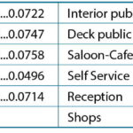
The number of car decks and the type of vehicles (mix of private cars and trucks) carried on each of them are controlled by a series of user-defined parameters, in accordance with the size of the designed vessel. Smaller vessels have usually only one deck for the carriage of trucks and private cars. For larger vessels, an additional upper deck for the carriage of trucks and/or private cars and/or one or two lower holds, forward of the engine room, located inside the B = 5 limit plane for the carriage of private cars may be created, according to user specifications. Alternative layouts with central or side casings may be modelled, as specified by the user. A number of upper decks are then generated, providing the necessary space and area for the accommodation of passengers and crew, public facilities, according to the passengers transport capacity specified by the user and the required crew number, calculated according to Greek statutory regulations. The upper decks’ layout considers also the accommodation of the vessel’s life saving equipment required for the particular service (i.e. life boats and / or life rafts).
Fig. 3 shows an example of the resulting general arrangement of a large RoPax vessel, developed by the parametric design software. This vessel, with a transport capacity of 1600 passengers (750 berthed), 102 trucks and 125 private cars, has three accommodation decks, a main and an upper car deck for the carriage of trucks and two additional garage spaces in the lower holds, carrying private cars.
3.4 Preliminary structural design
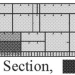
The preliminary scantlings are determined by an external software tool that has been purposely developed and linked to the geometric design environment to acquire the relevant geometric data, Katsaounis et al. (2006). This software tool incorporates all the basic requirements of the Det Norske Veritas rules for the structural design of RoPax vessels. The ship is longitudinally subdivided into three main zones, Fig. 4, separating the midship area from the structurally more complex forward and aft end areas, allowing the use of different shipbuilding systems (longitudinal or transverse stiffening) in each zone. Each zone is further subdivided into sections between successive transverse bulkheads. The sections are vertically subdivided into sub-sections between successive decks up to the strength deck, above which the superstructures sub-sections are defined. The topological details of the various bottom, side and deck structural elements in each sub-section are subsequently defined.
After defining the geometry of the various areas of the ship structure, the local loading calculations are performed and the maximum allowable stresses for the local strength analysis are determined according to the DNV Class rules. A reasonable margin, accounting for the stresses due to the hull girder bending is included. The required plate thickness, along with the section modulus and other cross-sectional characteristics of the primary and secondary stiffeners are subsequently calculated.
Based on the above requirements, the selection of structural members is finalized with an appropriate corrosion thickness allowance. Secondary stiffeners, minimising the combined plate-stiffener weight are selected from a data base. For the primary stiffeners, built-up cross sections, minimising steel weight while satisfying all structural requirements and geometric constraints are evaluated.
3.5 Weight calculation
The vessel’s light ship weight is subdivided into the following main weight categories: structural, propulsion, auxiliary, deck machinery and outfitting, electrical, piping, heating and air-conditioning, accommodation and miscellaneous. With the detailed geometrical model of the vessel’s hull form and of the internal layout readily available from previous steps, the structural weight is obtained by direct calculation, namely based on the results of the structural analysis module. The machinery weight is decomposed into several sub-items (main engines, gear-boxes, shafting, propellers, steering gear). The other main weight categories are also further decomposed into sub-categories. Relevant empirical expressions have been developed for the estimation of the corresponding weights and their centres. Some examples of the used semi-empirical formulae are presented in the following.
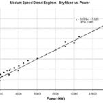
The dry weight of a medium-speed Diesel engine is approximated by a semi-empirical formula, based on the engine’s power PB in [kW], Fig. 5:
WDE = 0.009 · PB + 5.63 [t] (5)
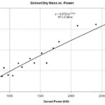
The weight of a Diesel driven generator with power P is approximated by, Fig. 6:
WDG = 0.0721 · P0.8123 [t] (6)
The weight of a shaft line (per running meter) is approximated by, Fig. 7:
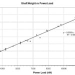
WSL = 0.0001 · SHIP – 0.0668 [t/m] (7)
The outfitting weight of the accommodation decks is calculated using weight coefficients per square meter, Table 1. The above semi-empirical coefficients were compared with available data from a number of existing vessels and appropriate correction coefficients were deduced for fine-tuning. The vessel’s maximum payload is determined by subtracting the light ship weight and the various deadweight items (consumables, provisions, stores, etc.) from the total displacement. The various semi-empirical coefficients presented above are the default values used by the software, unless the user specifies specific values.
3.6 Intact and damage stability analysis
The stability analysis verifies regulatory compliance for intact and damaged condition. Intact stability analysis is based on the requirements of IMO Resolution A.749. The SOLAS ’90 damaged stability criteria, Resolution 14 (Stockholm Agreement) or the IMO probabilistic procedure (Resolution MSC 216(82)) may be used for the damage stability evaluation, according to the user’s requirements. A series of macros has been prepared to control the process flow, while the actual stability analysis is performed using the calculation capabilities provided by NAPA. The intact stability calculations and the deterministic damage stability calculations are performed for a predetermined range of initial draughts at zero trim and also for six specific loading cases with 100 % passengers combined with 100 %, 30 % and 0 % vehicles loading, both in the departure and arrival condition. The probabilistic damaged stability calculations are performed for three initial draughts, according to the provisions of Resolution MSC 216(82).
3.7 Assessment of economic performance
The building and operating costs are decomposed into a hierarchy of cost items. These items are estimated by semi-empirical formulae, fine-tuned in comparisons with existing ships’ data. In general, building cost calculations are based on unit construction or procurement costs (e.g. cost of fabricated steel or aluminium per ton, cost of accommodation or public spaces outfitting per square meter, cost of propulsion machinery per kW). Most operating cost items are also estimated on the basis of corresponding unit cost values. Since these unit costs vary considerably from year to year or from one shipyard to the other, the user can specify the corresponding unit values or take default values of the software. Unless user specified, the crew number and synthesis and the corresponding monthly costs are determined according to Greek statutory regulations.
The operating cost and annual income are calculated for the particular service conditions specified by the user (length of route, service speed, fuel price, number of trips per week in the low, medium and high season, the estimated passenger and vehicles occupancies along with the corresponding passenger’s fare and vehicles freight for each of the three operating seasons etc.).
The user defines also the expected years of operation, the estimated vessel’s price at the end of the operation period (as a percentage of the corresponding acquisition cost), the percentage of the initial acquisition cost covered by a loan, the loan interest and the payback period, the discount rate and tax rate. Based on these data, the vessel’s economic performance is assessed using appropriate economic criteria, such as the Required Freight Rate (RFR), or the Net Present Value (NPV).
4 Integrated optimization environment
The parametric design software has been linked to the multi-objective optimisation software modeFrontier to form an integrated design and optimization environment. A Genetic Algorithm was selected for its inherent capability to deal with multi-objective optimisation problems with mixed continuous-discrete variables and discontinuous and non-convex design spaces.
4.1 Objective functions
The user has the choice of various technical or economic objective functions. Minimization of building and operating costs and maximization of annual revenues are simpler examples of available economic objective functions. However, more complex economic criteria like Required Freight Rate (RFR) or Net Present Value (NPV) are considered more suitable. Propulsion power can be used as a separate objective function, although its effect is indirectly accounted for in RFR and NPV via the operating and building cost.
Maximization of stability margins may be used as objective function, Zaraphonitis et al. (2003), Boulougouris et al. (2004). Alternatively the user may treat stability (and safety) characteristics as constraints. Similarly, seakeeping performance may be expressed by objective functions or constraints, specifying acceptable seakeeping criteria/limits regarding the vessel’s performance (motions, accelerations or sea-sickness index) in specific sea states; appropriate links between the design environment and seakeeping codes enable the assessment of the vessel’s response in a seaway. Further objective functions can be used as required, since the design software architecture is flexible and the employed optimization method multi-objective by nature.
4.2 Demonstration studies
The developed methodology was applied to the design and optimization of three RoPax vessels:
• Ship 1: 500 passengers (8 berthed),
9 trucks (or equivalent number of cars), VS = 18 kn
• Ship 2: 590 passengers (33 berthed),
12 trucks, VS = 19.5 kn
• Ship 3: 1300 passengers (308 berthed),
35 trucks, VS = 23.5 kn
All vessels were considered operating for 20 years in a 21 nm route, connecting the port of Kylini in the west coast of Peloponnese with the island of Zakynthos in the Ionean Sea.
Following a ship owner’s perspective, the NPV was used as sole objective function. This is a complex criterion, encompassing the building and operational costs, as well as the annual revenues. Transport capacity and propulsion power are therefore indirectly accounted for. Suitable constraints were introduced, enforcing intact and damage stability requirements. The Multiple Objectives Genetic Algorithm optimisation scheduler was selected with an initial population of 24 (randomly generated) designs. The optimisation process was subsequently initiated for 100 generations with a 0.5 probability of directional crossover, 0.05 probability of selection and 0.1 probability of mutation.
For Ship 1, the initial generation NPV varied from 4.22 m€ to 8.19 m€ . However, only 8 (= 33 %) initial designs were feasible, with NPV between 7.25 m€ and 8.14 m€. In the subsequent generations, the number of unfeasible designs decreased substantially, while NPV increased. Within the six generations, the maximum value of 8.63 m€ was reached. Calculations continued for a total of hundred generations, but the NPV value was not increased further. The maximum NPV was obtained for a design with Lpp = 79.60 m. The design maximizing NPV had very low power requirements due to a high L / B ratio and low building cost values, very close to minimum building costs for all considered designs.
For Ship 3, the initial generation NPV varied from 30.01 m € to 38.64 m €. Only six(= 25 %) designs were feasible, with NPV varying between 33.74 m € and 38.64 m €. Again, the number of unfeasible designs in the subsequent generations decreased substantially, while NPV gradually increased. The design with maximum NPV (41.0 m €) was found within eight generations. The maximum NPV was obtained for a design with B = 22.45 m. Similar trends were observed in the results of comparable optimization studies performed for vessels of medium transport capacity, Zaraphonitiset al. (2007).
5 Elaboration of the optimum designs
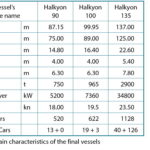
The resulting optimum vessels were further elaborated. Table II summarizes the main characteristics of the resulting designs code named »Halkyon 90«, »Halkyon 100« and »Halkyon 135«, respectively.
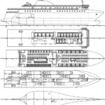
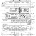
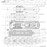
The complete 3D models of the steel structure of the three vessels were developed using the Tribon Hull software by the collaborating Elefsis shipyard, including general arrangement, classification drawings, shafting arrangement, piping drawings, electrical installation drawings, exhaust system, etc. Detailed calculations of weights and costs verified the results of the parametric design software. Fig. 8 to Fig. 10 show the final general arrangements for the three vessels.
»Halkyon 100« was selected for further elaboration to contractual design level, including a detailed numerical and experimental hydrodynamic analysis, numerical structural analysis, and noise and vibrations calculations. Alternative arrangement drawings for the passenger accommodation spaces were developed to meet different ship owner’s requirements. Finally, a detailed shipbuilding specifications document was prepared.
5.1 Hydrodynamic analysis
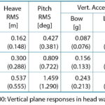
Resistance and seakeeping tests were performed at NTUA, using a 4.0 m long model of the »Halkyon 100« vessel. Numerical seakeeping predictions with the strip method SPP-86, Loukakis et al. (2009), were compared with experimental results for head seas. They were independently verified against a 3D panel method, Papanikolaou et al. (1992). Table 3 compares results for vertical plane motions and accelerations for a speed of 17 kn. HS describes the significant wave height, TP the wave peak period, LCG the longitudinal centre of gravity, RMS the root mean square value. Based on the SPP-86 results, an operability analysis for the selected vessel in typical Aegean Sea conditions was performed. A 6.5 m long model was constructed to perform wake measurements and self-propulsion tests. Finally, the Dynasim software was employed to investigate the vessel’s manoeuvring characteristics, Spyrou and James (2006), Chahine et al. (2003).
5.2 Detailed structural analysis
The DNV software package Nauticus Hull Wave Load Analysis was used for the numerical analysis of the longitudinal strength and local strength calculations, Varvarigos et al. (2006a) Varvarirgos et al. (2006b). For the longitudinal strength calculations, the ship was modelled up to the boat deck, excluding the aluminium superstructures. Calculations were performed for the full load departure condition, with 19 trucks and three cars on the car deck and 800 persons on board, passengers and crew. Mild steel with yield stress 235 MPa was used for the ship structure, except for the car deck plating and secondary longitudinal stiffeners, for which steel with yield stress 355 MPa was selected. First, the complete geometric model of all structural members was developed. The final finite element (FE) model was then created using 4-node quadrilateral or 3-node triangular plane shell elements for the plating with six degrees of freedom (DOF) per node, and 2-node beam elements for the stiffeners, again with 6 DOF per node. Pillars were modelled by 2-node truss elements with 3 DOF per node. The FE model developed had approximately 140,000 elements.
Detailed stress and displacement results were derived for all structural parts of the bottom and side shell, double bottom floors, decks and transverse bulkheads. The most heavily loaded area was found to be the bottom plating between frames 18 and 36, in hogging condition.
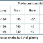
Table 4 presents the maximum stresses developed on the plating of the hull shell, together with the corresponding safety factors against yield, for the three conditions studied. Safety factors SF were calculated with respect to the Von Mises stresses, indicating that the worst condition is hogging. Similar tables with maximum stresses were calculated for the plating and stiffeners of all structural parts of the hull, resulting in quite higher safety factors than in the case of the hull shell plating. In addition to the above results, the longitudinal strength analysis revealed two areas of the upper deck (z = 11.1 m) exhibiting excessive vertical displacements (but not excessive stresses) and which probably need an increase in their stiffness. Local strength calculations for the car deck used a very dense FE mesh. Two regions of the car deck were selected and modelled, one between frames 36 and 51 and the other between frames 78 and 87, representing the worst case scenarios and analysed under the combined action of the hull girder bending loads and local loading from the truck and car wheels. Their structural response was investigated under five different wheel loading scenarios, varying the position of truck and car wheel footprints with respect to the transverse stiffening members. 4-node, 6 DOF per node quadrilateral plane shell elements for the plating and 2-node, 6 DOF per node beam elements for the stiffeners were used to create both deck parts models. Their mesh was quite dense, with plate elements having a dimension of approximately 100 mm. As expected, stress concentrations are observed at the wheel footprints.
6 Conclusions
An integrated methodology for the preliminary design, evaluation and optimization of RoPax vessels has been presented. The core of the developed procedure encompasses the parametric design of RoPax vessels, based on a selected set of design parameters. Suitable macros have been developed for the design of the vessel’s hull form, internal layout and the preliminary structural design evaluation. Additional modules have been developed to perform relevant calculations for the evaluation of the design, including stability analysis in intact and damaged condition, powering estimation and finally the assessment of the economic potential of the vessel. All these modules are integrated in a design environment, facilitating the development and evaluation of a large number of design alternatives in limited time.
To further increase the effectiveness of the developed procedure, the parametric ship design application has been linked to a multi-objective optimization tool, facilitating the design space exploration in a rational and efficient way. To demonstrate its potential, the developed design methodology has been applied to the design and optimization of a series of RoPax vessels. The resulting designs have been further elaborated up to the contractual design level by the design team partners Elefsis Shipyards and NTUA.
A. Papanikolaou, G. Zaraphonitis, S. Skoupas, E. Boulougouris


