Synopsis
The continuing trend to higher powers coupled to larger rpm can cause problems with vibrations in tugs[ds_preview]. Higher powers are installed into smaller and more lightweight hull constructions. At the same time the demands for smooth operation with low vibration levels come into the foreground for reasons of comfort together with a more proven knowledge on the influence of vibrations on component lifetime.
At each point where the propulsion systems interact with the ships, hull vibratory forces will be induced into the construction. This is inevitable and the ship’s construction should be such that it can absorb these forces. On the other hand it should be understood that the structural design of mainly the shaft line foundation and rudderpropeller ambient structure is significantly influencing the vibration level which is lead into the tugs hull and should therefore be subject of precise engineering not only with regard to strength but also to stiffness.
This paper describes aspects of the mechanical integration of rudderpropeller propulsion systems for tugs. It shows modern azimuthing propulsion systems (azimuthing propellers and shafting systems) and will highlight the advantages and dangers of different installations of shaft lines and rudderpropeller fastenings.
It will be shown what can go wrong and will present examples of shafting systems that are less sensitive to misalignments. The paper will also provide an insight in the typical excitation of ducted azimuthing thrusters. It will show some results of investigations into the magnitude of these excitations. By means of modal analyses, samples will be given of good and inadequate constructions.
1. Introduction
Schottel rudderpropellers have been serving tugs for more than 40 years and with a total number of about 800 tug boats equipped with Schottel rudderpropellers the company has gained a wide experience in supplying complete azimuthing propulsion systems consisting of fixed and controllable pitch rudderpropellers, shaft lines, hydraulic systems for steering, clutch and brake plus complete electric control systems including e.g. electrically driven azimuth steering, modern bridge panels and the popular Schottel Masterstick multi-unit control system.
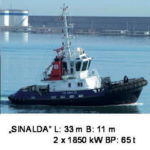
Over the years the tug boat has developed from a simply designed »working horse« for use mainly in harbour areas to a highly engineered complex ship system with a large scope of functions and specialized tasks. For many applications working hours and power density both have increased while hull sizes are often limited by reasons of manoeuvrability or reasons of costs (Fig. 1).
This higher engineering depth of the product »TUG« requires engineering support and continuous development efforts in all essential disciplines of mechanical, hydraulic, electrical and hydrodynamic engineering. Schottel has therefore built up specialised development teams of experienced engineers for all these four key competences supplying the companies’ sales and order management organisation with the engineering support that is needed to serve our customers needs.
As a further contribution to a high quality technical support of each individual order a team of engineers was added to the companies’ order management department to have a 100 % technical revision of the installations that are released to our customers.
By this organisation Schottel ensures to bring the state-of-the art knowledge from the R&D departments directly into the projecting phase of each individual order.
The typical order specific engineering support for the standard tug application includes engineering from all disciplines that have to be combined to a round package of system competence:
• bollard pull calculation & propeller blade design (optionally CPP propeller pitch range determination)
Design & calculations are made under consideration of motor capacity, thruster-hull-interaction and space & draft. The detailed propeller 3D-models are given to the foundry as to ensure precise propeller geometry.
o electrical design of the interfaces, switch boxes, operation panels and superior control systems
Based upon standard drop-in panel components and a modular switch box concept any arrangement of units with its design variants can easily be adapted. The CAN-bus system with its flexible interface possibilities allows safe data and signal exchange. The generation 3 Masterstick system offers one-hand operation of the ship.
• hydraulic & pneumatic engineering for steering, clutch, brake
Hydraulic plans and 3D-construction of the hydraulic aggregate give exact interfaces for the designer.
• check of strength of the mechanical fixation of the thruster to the hull design of the shaft line considering:
• strength requirements of the classification society
• distance and height difference between diesel and SRP
• axial movements of the components
• stiffnesses of the foundations and bulkheads
• excitations by unbalance and cardan joints
• thermal expansion of the shaft line itself
• Torsional-Vibration-Calculation / Lateral-Vibration-Calculation / Axial-Vibration-Calculation
The Figs. 6–8 show a typical installation space for a medium sized stern tug application, an example for a mass-elastic-system of a tug drive line and a calculation result of a modal analysis of an intermediate shaft.
The distance between motor and thruster, the axis offset of crankshaft to thruster input shaft and eventually the inclination of motor and/or thruster are the first main figures needed to make up a shaft line concept.
A Torsional-Vibrations Calculation is made for each individual project. Focus is on the dynamic torque load of the thruster makers’ scope of supply as a counter check of the official TVC, which is in the responsibility of the motor supplier. Torsional vibrations are not handled in this paper!
It should be understood, that excessive torsional vibrations can also excite the shaft line, the motor or even the thruster which will result in vibrations measured e.g. at the shaft line foundation.
When examining lateral or axial shaft line vibrations, the torsional vibration system should be studied beforehand, to prevent faulty conclusions.
Different from the TVC which requires data exchange between motor and thruster maker only, the Lateral-Vibration-Calculation has an interface to the designer/yard through the assumptions for bearing foundation stiffnesses that need to be made by the calculation engineer. Finally for all the a.m. technical issues an adequate data exchange between the technical people is substantial.
To get an overview over the organisation at Schottel that is involved into the engineering decisions during the project phase a simplified organisation chart may help to understand responsibilities and information flow.
This paper will address the mechanical engineering and especially the mechanical integration of rudderpropeller (SRP) and shaft line into the tug and is therefore reduced to those aspects.
The most important document which is released to the customer as a result of the project work is a detailed installation drawing showing the mechanical components in the ship structure supplied by the customer.
With the final acceptance of this installation drawing the order specific mechanical engineering in the order entry phase is closed and finished. This period of time should be used by both the drive suppliers and the customer to get all relevant aspects of the installation fixed to ensure trouble-free installation, setting into service and operation.
The following essay shall identify aspects and problems that have to be clarified within this task. Thumb values and examples will be given to quantify the one or the other parameter. Finally, in spite of the use of standardised components and methods every installation requires wary engineering and clean interface commitments. This again requires a clear and common understanding of the questions to be clarified on both sides. This paper shall help to identify the questions that should be asked.
2. Scope of order specific calculations
2.1 Scope of calculations on thruster
maker side
For each order a standard scope of calculations is made to ensure proper engineering of the propulsion system.
• calculation file of the SRP product is a standard package supplied to the classification society
• check of strength of thruster-to-hull connection (bolting, welding, structure)
• calculation of strength of shaft line
• lateral vibration calculation of shaft line
(with assumed or better known stiffness values)
• axial vibration calculation of shaft line
(axial stiffnesses of bulkheads and fixed bearing foundations must be supplied by customer)
• check of deflection/displacement capacity rad. & ax. (motor movements of elastically supported motors must be supplied by customer)
• TVC (torsional vibration calculation) as a counter-check to the official TVC supplied by the motor manufacturer to the classification society
This scope of calculations is managed by a team of engineers in the order management department who are responsible for the technical clarification of the order and thus to communicate between customer (over sales department), classification society and with the experts in the development departments on demand.
To find the best solution for each individual application a certain scope of information is required also from customer side.
2.2 Recommended scope of calculations and information from customer side
• check of structural strength or SRP foundation (hull-sided)
• check of modal behaviour of the the SRP units in the hull structure (resonances with 1st & 2nd blade harmonics to be avoided)
• shaft foundation stiffness to be ensured (design to 500 kN/mm – min. 300 kN/mm)
• supply axial stiffnesses of fixed bearing
foundations and bulkhead to thruster maker
• supply motor movements (6-degree-of-freedom calculation) to Schottel
The above list is limited to the mechanical aspects of drive integration into the tug hull. Strength aspects are generally under control and under tight observation of the classification societies. With regard to thruster and shaft line dynamics there is room for improvement and data and knowledge exchange should be improved by all parties involved.
3. The Schottel modular shafting system
3.1 Components used
As can be imagined by all the a.m. aspects of design and installation variants a huge portfolio of components agglomerates over years of application. This is not only hindering smooth logistic order handling but also bears an increased risk of running into technical problems. It was therefore decided to develope a standardised modular shafting system with a limited number of components with known and proven performance in the tug application. The »construction kit« for shaft lines comprises the following elements:
a) Bearings
For the loose bearing position split cylinder roller bearings and spherical bearings both of different sections are used. For the fixed bearing position the same types of bearing are used with axially fixation of the outer ring. Additionally a split double taper roller bearing type (developed and tested commonly with COOPER Roller Bearings Co Ltd.) is available in all required sizes which allows very high axial loads at a rather low minimum bearing load.
b) Shafts
Solid forged steel shafts made of 42CrMo4V with a max. length of 6 m are used most in the lower speed range, as stub shafts or for higher speed range with short shaft lengths. Flanges are shrink fitted with conical oil pressure assembly as a standard.
Seamless welded St52-3 with welded solid shaft/flange ends made of 42CrMo4V are mainly used as intermediate shafts, more for the higher speed range and for large installation lengths. Distances of ab. 6..7 m are spanned with hollow shafts with only two bearings. Using split bearings allows having the shaft flanges integrated into the welded end pieces.
Composite shafts are used time by time in special applications. For the tug application it must be said that a steel shaft is clearly more robust and thin-walled hollow steel shafts offer most of the advantages of the composite solutions at lower cost.
c) Compensation couplings
To compensate movements and deflections within the shaft line system a defined variety of components is nowadays used for the standard installations.
Cardan shafts, with the disadvantage of own excitation are used to compensate height differences between diesel flywheel and thruster input flange.
For the favourite straight shaft applications steel link couplings with metal joints (lower displacement capacities) or rubber joints (higher displacement capacities) are used at different positions in the shaft line.
As these couplings are radially stiff they can only compensate axial and bending deflection when used in single arrangement.
To compensate radial deflections or to adjust small height differences between shafts they are used in double arrangement with a piece of shaft in between to adjust the radial displacement capacity at given max. bending angle of the coupling.
Toothed couplings aren’t used that often because they again require regular maintenance and normally only have limited radial displacement capacity. Nevertheless they are often used to link two pieces of shaft together (to e.g. a longer intermediate shaft).
The graphics in Fig. 12 give an overview over the typical max. displacement values of the different coupling types and the required alignment accuracies. The coupling data are general values only. Specific values have to be taken for the respective size chosen.
Special advantage of the double arrangements with steel link or rubber link couplings is that they do not produce excitations as the cardan shaft but have sufficient displacement capacities as required from the installation. A trivial but important thing is to differ between alignment tolerances and displacement capacity in operation. Any alignment needs to leave sufficient margins for the operation deflections that will come on top of it!
3.2 The software tool
To make the choice of the components quick and easy and to have all necessary data available in one database Schottel uses an own software tool for the composition of the shaft line.
The so-called »shaft line generator« allows the composition of the shaft line under consideration of shaft strength, lateral vibration safety, required bearing lifetime and adequate cardan shaft size.
The basic strategy is to use max. three bearings per shaft whereas the centre bearing is the fixed bearing in this case to assure the minimum bearing load required. The user can choose the main order data, power and speed and the dimensional restrictions of the installation space. By adding preferences that can be made with help functions from the programme the user comes to a limited number of useful solutions for the power transmission task.
With the data generated the further calculations like TVC and LVC can be done upon stored databases and installation drawings can be produced for the customer.
To be continued in the following issue (HANSA 9/2010).


