Continued from HANSA 8/2010
4. State-of-the-art installations
4.1 Principal installation methods of the thruster[ds_preview]
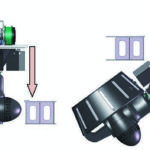
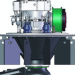
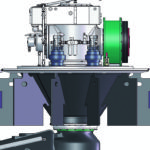
Dependent on the maintenance concept and constructive restrictions by the tug overall design the principal installation method can be chosen to be: a) from above (see Fig. 14 left), b) from below (see Fig. 14 right). In both cases the connection to the hull has to be designed to be:
• pressure water tight
• of sufficient strength
• of sufficient stiffness
a) Installation from above
Due to the large size of the structure supplied with the thruster there is a sufficient »part of the stiffness« already delivered with the thruster itself. Radial web connection to the hull is therefore normally not necessary.
b) Installation from below
Also for this method the thruster only needs to be connected to the hull flange via its top plate from a strength point of view. With respect to stiffness and consequently the dynamic behaviour of the thruster in the structure it is sometimes useful or necessary to also connect the brackets of the thrusters support structure radially with the trunks’ cylindrical wall. Care has to be taken to align the brackets with the hull structures’ counter webs.
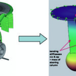
Compared to the fixation of the main flange only the bending stiffness increases approximately by ab. 10..25 % when the webs are connected. This will result in an offset of the pendulum mode of the thruster by ab. 5..10 % to higher frequencies. Pendulum mode means that the underwater masses of lower gear box, propeller and nozzle as a whole swing in the stiffness of mainly the steering tube of the thruster.
4.2 Installation variants
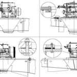
The graphics below show the standard fixation methods of the thruster to the hull structure. From the top left to the bottom right welded connection, bolted steel flange connection with O-ring sealing and bolted »rubber flange« connection with spacers that define the compression of the rubber flange are shown.
A formerly used method is the epoxy cast foundation which isn’t recommended any more because the other three variants meet the yards requirements at lower installation effort. All these installation methods can be used either with or without additional bracket connection in the trunk. As the brackets are also used to hold the bottom cover plate in are of the hull plating they are anyhow foreseen as a standard feature of the support structure of the thruster.
4.3 Design goal for thruster foundation stiffness
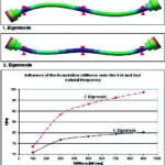
Finally with a specific thruster design the mass of the thruster and its mass moments of intertia especially around x- and y-axis (pendular modes) are known. With the thrusters’ own vertical (z-direction) and bending stiffnesses (x-, and y-direction) linked to the hull structures’ stiffness the Eigenmodes of the thruster are already determined. Furthermore the main excitation frequencies of the propeller (1st, 2nd and 3rd order of the blade number) are given by choice of the number of blades (four as a standard, sometimes five as a requirement from the TVC).
So there are not very much parameters left to tune other than the constructive stiffness of the thruster foundation and optionally the connection of the thruster brackets to the hull. Considering the thruster’s own mass-elastic data and its excitation frequencies some typical required values for the thruster foundation stiffness for the power range of 1,000 to 3,500 kW can be found with:
cxx & cyy > 3 x 10¹⁰ [Nm/rad]
cz > 3,5 x 10⁹ [N/m]
Detailed calculations should be made to avoid global resonances to the three critical mode shapes with the a.m. propeller orders to avoid needless high vibration levels in the ship or consequential damage in mainly thruster bearings and shaft line components.
4.4 Traditional and modern shaft line
arrangement
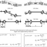
For many years the tug drives with azimuthing thrusters were built-up with a rather limited number of diesel motor types and with a tight speed range of mainly ab. 600..1000 rpm. The typical shaft line was constructed using:
• massive forged steel shafts only
• cardan shafts in Z- or W-arrangement
• all displacements were taken by the cardan shaft splined connections
• spherical roller bearing were used as fixed and loose bearings
• standard lithium-soaped multi-purpose grease was used
• foundation stiffnesses of 500 kN/mm were commonly reached with massive foundations
• bulkhead bearings were meant to be a »no go« due to the radial stiffness deviance compared to the other bearing foundations
Using a standard foundation stiffness and massive cylindrical shafts which were considered as simple »bending springs« the choice of the bearing distance (and hence number of bearings) was a simple job that could be solved by e.g. using selection diagrams for a specific combination of shaft diametre and bearing number. The higher the speed and the longer the shaft line the more bearings were used to solve the task which went well until 1,600 to 1,800 rpm diesels were widely used.
In extreme cases it became necessary to use an amount of up to six bearings in one shaft line and up to ten bearings in the arrangement of one azimuth drive! This demands a very good foundation design and requires extensive alignment which cannot always be realised in practice.
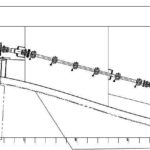
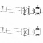
Figure 17 shows such a traditional arrangement which was often used also with higher rpm. With a good foundation design and proper alignment and maintenance many of these installations are in operation without problems. But it must be said, that also the most severe problems happened with these arrangements in high-speed applications; complex to analyse and with high effort to solve.
Today the aim is to solve the power transmission with the lowest possible number of parts (especially bearings) that require maintenance and to ease the installation and alignment. Every bearing position is also a potential excitation contact for structural noise and requires maintenance, alignment and foundation and is a subject to wear and limited lifetime.
In modern installations we often do not find a cardan shaft anymore because it is a vibration exciter on its own when used with typical deflection angles of 4–8°. By bringing the thruster into a hydrodynamic reasonable inclined position of ab. 3–6° (which also needs to be applied for the motor) a straight shaft line is reached.
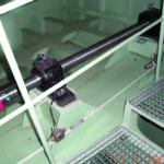
Using hollow shafts made of seamless tubes of high strength allows much wider spans of these shaft lines due to their high bending stiffness and low mass without a reduction of the natural frequencies of the shaft line. In this way very well-arranged installations are reached; easy to install, alignment tolerant and with low maintenance.
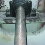
In the installation above the one and only bearing in the shaft line is located in the bulkhead. So the bearing housing flanged into the bulkhead is serving as bulkhead sealing as a double function. The only »foundation« effort for the whole shaft line is a hole cut into the bulkhead and occasionally some stiffening flat steels to tune the bulkheads membrane stiffness.
5. Typical problems or »What can go wrong?«
5.1 Thruster fixation – global resonance of the thruster in the ship structure
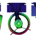
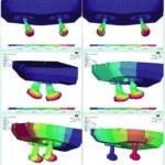
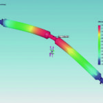
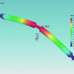
Independent from the installation method the worst thing that can happen is a global resonance of the thruster unit(s)! in the ship structure. The thruster together with its sister unit can perform pendulum and vertical vibrations both synchronous and in opposite phase. This delivers normally at least 6 relevant Eigenmodes of the thruster pair in the ship structure.
To determine these Eigenmodes the structural 3D model of the tug aftship (normally available) and a reduced model of the thruster is used to keep the whole model simple and fast to calculate. Mass supplements for the submerged surfaces have to be made to consider that the system is oscillating in water. When calculating pendulum modes of the thrusters the hydrodynamic mass supplement for the hull plating can be neglected due to the more local deformation area of the hull shell.
For the thruster submerged body the water supplement should be added for more exact examinations. For the pounding modes the water supplement gets more important for the hull shell and less important for the thruster. As long as comfortable distances to resonances are reached (e.g. >20 %) water supplements needn’t to be applied.
There are various recommendations available for water supplements for different submerged shapes. E.g. DNV offers values in classification note 30.5. and many other sources can be found in the world-wide-web.
The reduced thruster model is a simplification of the thruster detailed finite-element-model to a pendulum with similar properties. The task is to prevent resonances of the propeller blade orders with the above shown Eigenmodes. The only parameters to be tuned are the stiffness of the hull fixation and foundation and the number of propeller blades (normally to be chosen either four or five). Concerning the no. of propeller blades also the TVC may require a specific blade number with regard to torsional resonances in the drive train which has to be dealt with.
5.2 Shaft line – lubrication problems
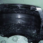
Roller bearings with grease lubrication are used as a standard for shaft lines in tug installations. It may appear trivial but still lubrication problems occur regularly in practise. Insufficient lubrication of the roller bearings due to inadequate type or insufficient amount of grease is the typical case. But even overfilling of bearing housings can cause problems after a while of operation / maintenance.
Most problems occur with overheated grease in high rpm applications (1,600/1,800 rpm). Few cases are known with insufficient maintenance because the necessity of maintenance of the bearings seems to be obvious for the operator and bearings are normally easy to access and under daily observation.
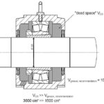
Bearing housings with a large »dead space« compared to the grease filling recommendation may be problematic especially when using high temperature grease with stiffer consistence at operation temperature (Fig. 23). Fewer problems are known with bearing housings with smaller »dead space« for high speed applications.
Schottel meanwhile uses high temperature grease as a standard in all shaft-lines that are supplied ready assembled to our customers. Standard grease is adequate and can be used for speeds up to 1,000/1,200 rpm. Maintenance manuals should be observed and individual consultation of service support should be used in case of doubtful lubricant or bearing condition or excessive operation temperatures (after running-in!).
Bearing temperatures measured on the housing surface in way of the outer bearing ring (on the bearing housing) shouldn’t exceed ab. 60 °C for standard grease and ab. 80 °C for high temperature grease (see table below).
A general comment
Cardan shafts contain eight needle bearings in their joints! A regular check of these joint bearings with respect to presence and condition of lubricant and condition of raceways is highly recommendable to prevent vibration due to play of the joints or even worse a fatal damage with the joint flying out of the shaft line. A regular check reduces risks and isn’t very costly as needle bearings are very cheap spares.
5.3 Shaft line –
»Why do shaft lines vibrate?«
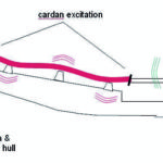
Shaft lines do vibrate because they are excited by dynamic forces mainly from dynamic reaction forces of the cardan shafts under torque and deflection and in rare cases by unbalance of the shaft system. These are the main sources for self-excited vibrations of the shaft line.
Vibrations can also be induced through the shaft line foundation. These vibrations could be named indirect vibrations and are mainly excited by e. g. diesel motor foundation excitations or thruster excitations induced via the thruster foundation.
The shaft line is a mass-elastic system and will react with forced vibrations which will be amplified when a resonance of the shaft line is hit. As the whole shaft line runs in air and foundations are normally welded constructions with rigid connections of plummer blocks to foundation the whole system has a very low damping which leads to high amplification factors in case a resonance is hit!
Unbalance problems appear especially with worn-out equipment or in consequence of assembly failures. Recommendations for the balance quality of the shaft components can be found in ISO 1940 and VDI 2060. A balancing quality of 6,3 or better should be aspired (which is easy to reach in practise).
Most regular the cardan shaft excitation and induced vibrations from the motor foundation make the problems. Cardan shafts:
• produce dynamic reaction forces onto the shaft line bearings with higher excitation frequencies at higher shaft speeds
(depending on W- or Z-arrangement, torque & deflection angle)
• additional dynamic components appear due to alignment failures that are unavoidable in real installations!
• an alignment accuracy of few tenth of a degree is required for cardan shafts
• deflection angles are normally chosen below 4° (max. 8°) to limit dynamic excitation forces
• cardan shaft excitation goes with 2nd order of the shaft revolutions (and its higher orders!)
• a sufficient distance of the 1st natural frequency of the shaft line to this cardan shaft excitation frequency is needed
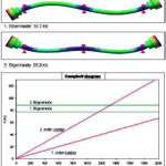
• the so-called Campbell diagram below shows the design goal
• Schottel designs the shaft lines with the 1st natural frequency being at least at 20 (15) % distance above the cardan shaft excitation frequency at nominal speed (undercritical design)
• overcritical design with the natural frequency being far below the nominal speed (e.g. in the range of idle speed to 50/60 % shaft speed is possible and useful but requires exact knowledge of the parameters
For the determination of the natural frequencies of the shaft line masses and stiffnesses of the shafts and bearings are known by the shaft line maker.
Bearing foundation stiffnesses must be agreed. Schottel requires a radial design stiffness of 500 kN/mm; 300 kN/mm are used in calculations; poor values of ab.down to 100 kN/mm are regularly found in real installations and cause severe problems!
It has to be considered, that the foundation stiffness is a linked serial stiffness of the bearing stiffness (roller contact), the bearing housing stiffness and the welded foundation stiffness.
The foundation stiffness in the a.m. range influences the natural frequency of the shaft line significantly.
• in cases of doubt Schottel evaluates the quality of the shaft foundation on request
• very often the shaft line foundation is not defined in the order entry phase, because steelwork for shaft line foundation is scope of work of the yard and so the designer just leaves some space for the foundation in its steel construction; this sometimes results in »uncontrolled« poor constructions
Bulkhead bearings are a special case. With the traditional shaft line designs with multiple bearings bulkhead bearings were normally prevented because of the »jump« in radial stiffness and the resulting undefined load situation for the bulkhead bearing.
With the modern shaft designs bulkhead bearings are used willingly because they:
• offer very high radial stiffness due to the bulkhead itself
• the bearing flanged into the bulkhead substitutes the bulkhead sealing
Problems occur especially when:
• the bearing is an axially fixed bearing and the axial stiffness of the bulkhead is insufficient
• the bulkhead bearing is used together with more than one additional bearing in the same shaft line
In the worst case the shaft line may run into resonance and an axial vibration of parts of the shaft line or the whole shaft line will appear. This normally results in a short-term damage of the bulkhead bearing or other axially moveable components of the shaft line like cardan shaft splined connection or deflection couplings.
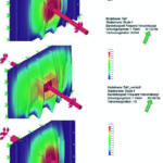
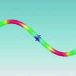
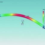
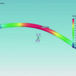
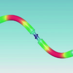
The figure series 33 shows what can happen and how it can be solved.
For a 1000 rpm application the main cardan shaft order of excitation is f = (1600 rpm / 60) × 2 = 33,33 Hz.
Obviousely (first picture) the mass-elastic-system of the shaft line (which is connected to the bulkhead via the bulkhead bearing) and the bulkhead (being a membrane spring) has an Eigenfrequency at ab. 31 Hz which would result in a resonance with the cardan excitation slightly below the nominal speed. This cannot be accepted and will clearly result in at least a very short lifetime of the bearing or even a fatal damage of the shaft line.
Such problems can be solved with low effort both in the design phase (change of axial stiffnesses or masses of shaft components / shaft separation) and also in case of detection in operation (additional stiffeners on the bulkhead).
In the mid picture of figure series 39 two simple flat irons running vertically left and right of the bulkhead bearing are used to shift the Eigenfrequency to twice its original value by stiffening! In the bottom picture the problem is solved by making the shaft more lightweight by using a hollow shaft of 220 × 8 mm instead of the solid 140 mm shaft. This results in a safe increase of the Eigenfrequency by almost 30 %.
To allow the prevention of this problem the axial bulkhead stiffness should be given to the shaft line supplier.
5.4 Shaft line – unallowable displacements
Displacements of the ship structure under sea load of the hull, deflections of the hull under thruster forces, thermal expansion and movements of the motor on its elastic mounts have to be taken by the shaft line.
In modern shaft lines with a low number of bearings over the shaft length and deflection couplings between shaft elements the radial displacements are usually not critical. More problems are found in axial direction both for static and dynamic displacements.
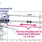
The example in Fig. 35 shall give some absolute values that can be found in a real application. In that installation with 11 metres distance between motor and thruster the following displacements occur:
• axial movement of the thruster input flange under thrust load in both directions (e.g. +/- 2 mm)
• thermal expansion of shaft line at differential temperature of the shaft of ab. 10..20 K (e.g. + 3 mm)
• axial movement of the diesel motor on its elastic supports (e.g. +/- 2 mm) (value to be taken from 6-deg-of-freedom calculation of motor maker)
• bending of aft ship structure under thrust load with effect on thruster-motor distance (can be neglected here)
As can be seen in the above example the totally needed axial compensation capacity of the shaft line is about 7 mm for a longer shaft line. Values can be somewhat higher for large boats or softer motor mounts. To manage these deflections compensation elements are used in the shaft line.
Most commonly steel link couplings with steel or rubber joints or toothed couplings are used for this purpose. These couplings are normally stiff enough not to influence the TVC and require no or only low maintenance.
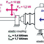
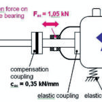
Most flywheel-mounted elastic couplings (chosen by Torsional-Vibration-Calculation result and usually scope of supply of the diesel motor manufacturer) allow significant axial displacements under a given axial stiffness. This displacement capacity can be used , but the axial reaction force onto the shaft lines’ fixed bearings has to be observed (see Fig. 36).
With bell-mounted elastic couplings with integrated output shaft the problem is often reversed which means that the bell-bearings are the weakest part in the axial chain and the problems occur in the motor makers scope of supply. Reaction forces resulting from the stiffnesses of the shaft line compensation couplings will apply axial and radial loads and also bending moments onto the bell bearings. Additionally these bearings are also suffering high vibration load and increased ambient temperature from the diesel motor.
Nevertheless, if properly designed and if all these aspects are kept in mind this solution is very favourite from the point of view of installation effort and the low number of components to be used.
As explained above the radial displacements are rather uncritical with the modern arrangements with minimum number of bearings per shaft length.
The following example shall give an idea of what are the limits in radial deflection:
With the required safety margin of 20 % the minimum 1st Eigenfrequency of a 1,600 rpm shaft line is:
fmin = 1,2 · 2 · 1600 [min-1] / 60 [s] =
0,04 · 1600 [s-1] = 64 [Hz]
for a shaft line with cardan shaft excitation. Of course in practise the shaft line is designed to a higher Eigenfrequency if possible to have some additional safety margin.
With this design the radial displacement capacity of the shaft line is ab. 14 mm at the bending fatigue limit of the shaft and ab. 9 mm at the required bearing lifetime of Lhna = 40,000 hours! This corresponds with a length of the shaft line of about 4,000 mm.
With this design the radial displacement capacity of the shaft line is 14 mm at the bending fatigue limit of the shaft and 13 mm at the required bearing lifetime of
Lhna = 40,000 hours! This corresponds to a length of the shaft line of 6,000 mm.
These values may explain why the radial displacement is not so problematic for the shaft line design. In fact a certain radial displacement is always present and helps to give the bearings additional pre-loading which reduces the risk of slipping due to under load.
Problems can anyhow occur when single bearing positions get under load due to radial movements of the foundations. On the other hand the above given values show, that a defined offset of the bearing positions during installation of the shaft line offers sufficient tolerance to load the bearings also by the shaft cross force under targeted bending of the shaft. This method isn’t common practise today but should be used without fear.
5.5 Shaft line – minimum required bearing load
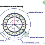
Any roller bearing used in shaft lines requires a minimum load to keep the rollers rolling instead of slipping or shifting (with unavoidable consequential damages)! If this minimum load is extensively undershot (see Fig. 44) slipping of the rollers will occur within short time.
The required catalogue values of the bearing makers are regularly not fully reached in reality even so most shaft lines run satisfactory and do not suffer slipping damages. This indicates that deviations can be accepted in practise. Nevertheless if the required values are considerably undershot it gets critical and damages can be expected.
For a given shaft size different bearing types with different section sizes and thus load capacity are used. This results in also different minimum loads required for these bearings made for the same shaft diametre.
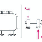
The formula below indicates the minimum required load for standard bearing types used in shaft lines. For spherical roller bearings the minimum radial load needed for grease lubrication is about:
Frad,min = 0,01 · C0 [kN]
with C0 being the static load capacity of the bearing taken from the makers catalogue [kN].
For cylinder roller bearings the minimum radial load needed for grease lubrication is about:
Frad,min = kr · (6 + 4n/nr) · (dm/100)2 [kN]
with: kr being the minimum load factor
n being the actual speed [rpm]
nr being the reference speed [rpm]
dm being the average of outer and
inner bearing diameter [mm]
For a given shaft diameter the minimum load of the strongest spherical roller bearing may be about 10 times the value of the minimum load of the smallest cylinder roller bearing section. This should be kept in mind.
Forced loading of the bearings can be made by radial offsetting of e.g. the centre bearing of a triple supported intermediate shaft or by radial offsetting of the diesel motor using the radial stiffness of the main elastic coupling to load e.g. the stub shaft bearings.
In case the calculation results show a bearing position being radially under loaded then this bearing should be used as the fixed bearing of the respective shaft. By this the rollers all over the bearing circumference are more or less equally preloaded and slipping risk is significantly reduced. This axial loading can also be done by using the downhill-slope force of an inclined installation.
5.6 Shaft line –
maximum axial bearing loads
Significant axial movements of the shaft line occur in any tugs’ shaft line (see 5.4). These axial movements multiply to axial constraining forces by the axial stiffnesses of the installed components. The resulting forces have to be taken by thruster input shaft, motor crank shaft and also by the shaft lines’ fixed bearings. Axial forces can be very high and have to be considered when choosing the section size of the fixed bearing.
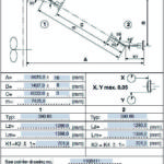
Another source for axial forces which is often underestimated is the friction force transmitted via the splined connection of the cardan shafts. The following example of a 3,000 kW / 750 rpm installation shows the problem:
• cardan shaft size: 390.80
• shaft torque: T = 38.200 Nm
• radius of the cardan shaft splined connection:
r = 92 mm
The resulting friction force that can be transmitted axially via the splined connection of the cardan calculates to:
Fax = µ · T / r = 62282 N!
with µ = 0,15 being the worst case friction coefficient of a poorly lubricated splined connection.
Of course this load will not appear constantly because vibrations and axial movements will make the splined connection slipping. But especially under running-up conditions with steady thermal growth of the shaft line the high axial force value can act onto the fixed bearing over a period of time which is critical for the fixed bearing with respect to overheating.
With the a.m. power and speed data normally a standard cylinder roller bearing could be used as fixed bearing of the intermediate shaft considering radial loading and required lifetime.
The axial load capacity of this bearing can be calculated to ab. 20 kN which is much less than required (see value above). The required bearing size is therefore e. g. a spherical roller bearing of the section size 23048 with much larger dimensions (see size comparison in Fig. 46).
Conical sleeves are normally used to clamp the bearing inner ring to the shaft line. It has therefore also to be checked, if the transmittable axial force of this clamped connection is strong enough to take the high axial load in cases like this one. Note that such cases normally only occur when higher axial movements are to be compensated in a shaft line in combination with low speed = high torque applications.
5.7 Shaft line –
unallowable bearing vibrations
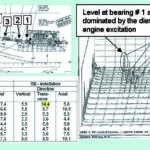
Different causes for shaft vibrations have been precedently addressed. Finally the vibration level should be measured during the setting-into-service of the tug. Permissible values are given in Fig. 47. Values should be measured as RMS (root mean square) values over a frequency range of 4–1,000 Hz. As long as the values in Fig. 53 are kept a short term failure of a shaft bearing isn’t probable.
Nevertheless damages can also occur when vibration levels are in the green range (e.g. lubrication or under load problems due to misalignment).
Advice for the execution of the vibration measurements on such shaft lines will be found in ISO 20283-4 which is under development.
Generally it should be observed to measure the fixed bearings in all three main directions whereas the loose bearings are measured in the two radial directions only. Nevertheless with very high and soft bearing foundations or with loose bulkhead bearings excessive axial vibrations of the foundation can cause problems with the roller bearings especially with spherical bearings, because the outer bearing ring cannot follow the very quick vibration movement and will wear out in the housing and the outer ring will axially hammer into the rollers within the axial bearing play. Both effects can cause bearing damage.
Special problem stub shaft vibrations
The picture below shows the problem of diesel motor vibrations induced to the stub shaft bearings especially to the bearing close to the motor. It is a general recommendation to have the stub shaft sitting on a foundation which is well connected to the motor foundation to prevent excessive radial movements of the motor to the stub shaft. The disadvantage of the good connection of the foundations is the regularly higher vibration level of the stub shaft foundation in excess of values as given in (Fig. 47).
The motor permissible foundation vibrations range about 25 mm/s and values in that region and in excess of it are often measured on the stub shaft (see Fig. 48, example of vibration measurements on a standard shaft line).
As the roller bearings accept higher vibration levels at higher preload a useful trick is to use the radial displacement capacity of the torsional-elastic coupling on the flywheel to radially pre-load the stub shaft bearings within its allowable limits with regard to bearing lifetime. In this example of a 1,650 kW / 1,000 rpm application the shaft diameter is 140 mm and the radial load of the bearings is ab. 1,800 N by the weight of the shaft.
The dynamic force component of the cardan shaft running at 4° deflection angle is already 1,500 N acting in the horizontal plane. The radial stiffness of the double-row elastic coupling is 2,4 kN/mm. The permissible continuous radial offset of the coupling is 7 mm.
The limit load of the spherical roller bearing type 23028 (smallest bearing section for that shaft diameter) at Lh10 = 20,000 hours nominal lifetime is 55 kN which gives enough margin for pre-loading. The minimum load (catalogue value) for this bearing to be safe against slipping is 6,8 kN. So a radial displacement of about 2–3 mm can be chosen which will result in ab. 8 kN pre-load of the bearing which will work well in practise.
Still the elastic coupling will have sufficient radial displacement margin to take tolerances from the alignment and operation deflections of motor to shaft.
To be continued in the next issue.
M. Heer


