Research report on main recovery-related problem areas in the rescue of persons in distress at sea and recovery-related requirements to be met by life-saving appliances
1 Foreword
In 1979, the dangers involved in the vertical recovery of persons from the water, especially those[ds_preview] suffering from hypothermia and exhaustion, were brought to the attention of the general public as a result of the fatalities during the Fastnet Race in the Irish Sea. Fifteen years later, Dr Wolfgang Urbach, a major in the medical corps of the Federal Armed Forces, stated: »A life-saving appliance for use in rough seas for the horizontal and gentle recovery of persons is not available anywhere in the world.«
Another 13 years later, in a series of articles published in 2007, Captain Peer Lange from the Ship Safety Division of Berufsgenossenschaft für Transport und Verkehrswirtschaft* [short: BG Transport] (formerly the Ship Safety Department of Seeberufsgenossenschaft), also came to the conclusion that there had been no decisive improvements compared with the situation in 1994.
However, against the background of further serious maritime accidents, the International Maritime Organization (IMO) had, in 2006, called for seagoing ships to be equipped, as of 2012, with life-saving equipment with the help of which ten persons per hour could be taken on board with a significant wave height of 3 metres. It has not been possible to achieve this objective for a seagoing ship in a cost-effective manner using the life-saving appliances available to date.
The Rescue Lifting System (RLS) research project, conducted by Hildesheim University of Applied Sciences and Arts, has been working in this field since 1989, exploring options for technical solutions to the problem of recovering persons from rough seas in a manner that is largely horizontal, to minimize the risk of shock. In 2006, its activities were widened to cover work on a cost-effective solution for commercial shipping.
The research activities were carried out in close cooperation with
• the SARRRAH project (Search and Rescue, Resuscitation and Rewarming in Accidental Hypothermia), a collaborative project involving the German Maritime Search and Rescue Service, Bremen, the Naval Institute of Maritime Medicine, Kronshagen, supervised by the Department of Anesthesiology, University Medical Center Schleswig-Holstein (UK S-H), Campus Lübeck, coordinated by Dr. Wolfgang Baumeier;
• the coordinating Ship Safety Division of the BG Transport represented by Captain Peer Lange;
• the School and Training Centre for Maritime Policing of the Federal Police (Maritime), supervised by Chief Inspector Lademann.
2 Research bases and procedures
2.1 Research findings taken into account
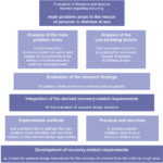
With the research findings described below (literature, lessons learned), the Forschungs- und Konstruktionsbüro Prof. Michael Schwindt, RLS – Rettungstechnologie GbR, Hildesheim, working in close cooperation with the aforementioned and following institutions (research establishments, universities / higher education institutions), was able to make a contribution towards solving the problems associated with recovering persons from the water in rough seas from merchant ships in a manner that minimizes the risk of shock.
2.2 Methodology and structure of the procedures
3 Main problem areas in the rescue of persons in distress at sea
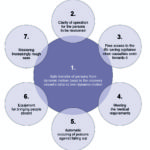
On the basis of an analysis and representation of recurring main problem areas in the rescue of persons from the water, it has been possible to pursue newer innovative approaches and methods. The following main problem areas and tasks of a recovery operation and appropriate recovery equipment, which are to be addressed by recovery technology, emerged as the most significant:
1. Safe transfer of persons from dynamic motion (sea) to the recovery vessel’s (ship’s) own dynamic motion.
2. Clarity of operation and purpose of the life-saving appliance for the persons in the water who are to be recovered.
3. Free access to the life-saving appliance when casualties swim towards it.
4. Meeting the basic medical requirement that persons be recovered in a manner that minimizes the risk of shock.
5. Automatic securing of persons against falling out to ensure that they are safely brought aboard and protected against being injured by the life-saving appliance and the side of the ship.
6. The equipment for bringing people aboard (launch and recovery equipment).
7. Mastering increasingly rough seas with wave heights of up to at least 3 m.
These main problem areas are closely interrelated and in some cases are mutually dependent.
In other cases, however, they are diametrically opposed to each other, which has made technical realization significantly more difficult because of the conflicting requirements. Extremely time-consuming and diverse practical trials under real-life conditions at sea were therefore necessary before it was possible to find adequately simple and effective solutions. The diagram (Fig. 3) shows the evaluated main problem areas in their relationship to the basic requirement for safe transfer from one dynamic system to another. The following points explain in detail the main problem areas and their solutions.
3.1 Safe transfer of persons from dynamic motion (sea) to the recovery vessel’s (ship’s) own dynamic motion
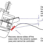
Five diagrams illustrate the impacts in an unregulated and a regulated transfer.
3.1.1 Impacts of ship roll and seaway
The diagram shows the impacts of ship roll and seaway on the distance (length of crane cable) between the head of the crane boom and a recovery device floating on a wave. This determines the length of the crane cable between the boom head and the recovery device which is necessary in this position.
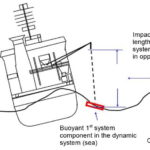
3.1.2 Impacts of ship roll and seaway moving in opposite directions
Figure 5 shows the impacts of ship roll and seaway moving in opposite directions on the distance (length of crane cable) between the head of the crane boom and a recovery device floating in the trough of the waves. This requires a significantly greater length of the crane cable between the boom head and the recovery device compared with Figure 1.
3.1.3 Negative impacts of ship roll and seaway
Figure 6 shows how the dynamic systems moving in opposite directions have a negative impact on the length of the crane cable and how, as a result, the controllability of the recovery operation from the deck of the ship is prevented by turbulence in the recovery area.
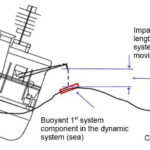
3.1.4 Uncontrolled change in the length of the crane cable
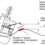
Figure 7 shows the uncontrolled change in the length of the crane cable as a result of the influence of the dynamic systems (sea and ship) and their negative impacts on the life-saving appliance as a result of hazardous kinking and hazardous changes in the position of the recovery device in the area of the ship’s side.
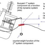
3.1.5 Advantage of the counterweight function
Figure 8 shows the advantage of the counterweight function of a second recovery system component that has been combined with the buoyant first recovery system component.
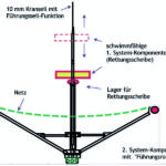
By means of its counterweight function, the second recovery system component ensures that the crane cable remains vertical, adapting it to the dynamic motion in opposite directions, and means that there is no need a for a costly electronically controlled swell compensator. Thus, in one of the design variants derived from this, the crane cable can serve as a guide cable for the first recovery system component sliding up and down on the cable in the seaway. In other variants, the slack of the crane cable caused by the seaway is deflected behind the float of the life-saving appliance by means of a counterweight (see Figures 23 and 24).
Experimental evidence proving the feasibility of the counterweight function on the crane cable and the buoyant first recovery system component is available from:
• the Large Wave Channel at the Coastal Research Centre in Hannover (max. 2 m wave) and
• practical trials at sea with wave heights of up to 4 m in the North Atlantic and further
• trials at sea with different sizes of ship and wave heights up to 3 m, as described in Section 3.7
3.2 Clarity of operation for the persons to be recovered
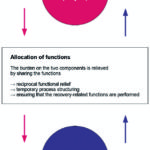
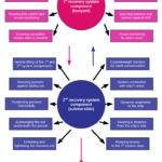
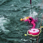
If the counterweight function of the second recovery system component is combined with further recovery system components, the buoyant first recovery system component can be designed as a rescue disc, like a lifebuoy, which slides up and down freely and automatically on the crane cable or crane cable forerunner and adapts to the seaway. Figure 10 shows which functions each of the two recovery system components performs.
3.2.1 Clarity of operation of the first recovery system component
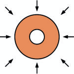
By combining the counterweight function of the second recovery system component with further functions, the buoyant first recovery system is relieved of other functions, and its operation is thus clear to a person adrift in the sea. In keeping with the principle of a lifebuoy, the circular shape of the buoyant first recovery system component ensures access over an arc of 360 degrees. Access area = 100 % when the second recovery system component is submerged. Its operation is clear to persons to be recovered.
3.2.2 Clarity of operation of the second recovery system component
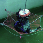
The second recovery system component combines the counterweight function with the function of picking up a person under water by submerging a stretched net below the trough of the waves. The second recovery system component is not visible to the person to be recovered as they swim towards its and thus does not result in any confusion about how to operate the life-saving appliance. This guarantees clarity of operation.
If the second recovery system component is designed such that it exhibits a collapsible frame for a net stretched across it, the persons are secured and positioned horizontally, as medically required, by lifting the second recovery system component with the crane. The persons to be recovered do not have to assist in their rescue.
Ratio of dimensions in percent between the first recovery system component (buoyant) and the second recovery system component (submersible)
1. Area of the first recovery system component (buoyant)
Given: radius of the rescue disc (rRS) = 33.0 cm
Calculation with formula: ARD = r2 · (where = 3.14159)
ARD = 33.02 · 3.14159 = 3,421.1944 cm2 3,421.2 cm2
The area of the first recovery systemcomponent is 3,421.2 cm2.
2. Area of the second recovery system component (submersible)
Given: radius of the net support surface (rSS) = 138.0 cm;
Apex angle ( ) in degrees = 30; reference surfaces (RSSS) = 6
Calculation with formula: ASS = (( cos( ) · r) · (sin( ) · r)) · RSSS
ANL = ((cos (30) · 138.0) · (sin (30) · 138.0)) · 6 = (119.5 120) · 69 · 6 = 49,680 cm2
The area of the second recovery systemcomponent is 49.680 cm2.
3. Calculation of the support surface during the lifting operation
Given: Area of the first recovery system component
(ARD) = 3.421,2 cm2;
Area of the second recovery systemcomponent (ASS) = 49,680 cm2
Calculation with formula: ALO = ASS – ARD
ALO = 100 – (3,421.2 · 100/49,680) = 100 – (6.88 6.9) = 93.1
The support surface during the lifting operation is 93.1 %.
To keep the net support surface free, the construction has a plastic bearing on which the first recovery system component rests when it is lifted out of the water. As a result, the first recovery system component is lifted together with the second recovery system component and the support surface is kept free.
Figure 14 shows how the first recovery system component is automatically supported when the second recovery system component is lifted.
Available support surface after the first recovery system component (buoyant) has been supported by lifting the second recovery system component (submersible) out of the water:
Given: Support surface during the lifting operation (ALO) in percent = 93.1;
Central area under the rescue disc (ARD) in percent = 6.8
Calculationwith formula: ASS = ALO + ARD
ASS = 93.1 + 6.8 = 99.9
The available support surface is 99.9 percent.
Experiments to prove the clarity of operation were carried out
• at the Coastal Research Centre, Large Wave Channel
• in practical trials at sea with different sizes of ship and wave heights
• and at a seafarers’ school with numerous test persons.
To be continued in the next issue.
Author:
Professor Michael Schwindt
Forschungs- und Konstruktionsbüro Prof. Michael Schwindt
RLS – Rettungstechnologie GbR
Rolandstr. 35, 31137 Hildesheim, Germany
Professor Michael Schwindt


