Andrew Gordon, Regional Manager Marine from Aveva, takes a look at the piping process – from system design through to installation – and its specific requirements in the shipbuilding industry
The importance of the process
Shipbuilding projects have complex schedules, require sophisticated design capabilities, create staggering amounts of[ds_preview] data and documents, and use large quantities of materials and resources. Shipyards therefore need highly developed capabilities for generating, coordinating and managing the complex interplay of information, materials allocation and resource availability within increasingly demanding time schedules and costs.
Wrong decisions based on incomplete or inaccurate information can be very costly. Communication failures within the design processes may lead to expensive rework later in the project. Lack of integration between design planning and production planning could lead to late availability of drawings. Lack of integration with planning and materials management results in materials not being in the right place at the right time.
The fabrication and installation of pipework is one of the major processes in shipbuilding. Many software tools are available for modelling the three-dimensional layout of pipes and in-line components, and for the creation of production information and numerical control data for the fabrication of pipe spools.
The efficient design and fabrication of ships’ piping systems may be hampered by a number of factors, including:
• a lack of integration between the software tools used, making it necessary to transfer data between systems or even to re-input information that is already available in an electronic format;
• the need to coordinate pipe routing with other shipbuilding disciplines such as hull structure, mechanical engineering, Heating, Ventilation and Air Conditioning (HVAC), electrical or outfitting, and to avoid clashes, dead spaces and access problems;
• problems with interdepartmental coordination arising from the need to create pipe penetrations that are acceptable both from the hull structure and pipe design viewpoints;
• the need to maximise the pre-outfitting of hull blocks to achieve an efficient build strategy and schedule.
The pipe design and fabrication process described below is an idealised process using tools available in the Aveva Marine suite of programs. Similar processes may be possible using alternative software systems or customised combinations of these.
Piping schedule and identification of special materials and equipment
The creation of a realistic schedule for piping design and fabrication is important for an efficient project, especially the timely identification and procurement of long lead-time items. Using a shipbuilding-specific planning and materials system allows the early definition of such schedules, based perhaps on similar previous projects. Early Bills of Materials (BoMs) are defined and linked to the activities in the schedule. This enables the material quantities and items in the parts list to be reserved for specific purposes and the latest dates for purchasing and delivery derived in accordance with the project plan. As the design progresses, the early BoMs will be regularly updated from the detailed design.
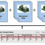
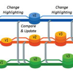
At this early stage, information about the various piping systems may still only be available as stand-alone lists of systems and equipment items, but it is important for other disciplines to be able to see and work with such information as early as possible. By importing such lists or datasets into a single engineering database, each discipline is able to use data issued from other disciplines, while retaining full control of their own data (see Fig. 1). Compare and update utilities highlight any inconsistencies between datasets imported from different sources. The early identification and correction of these ensures that all disciplines work with common and consistent information, maximizing design quality and eliminating problems which can be costly to rectify later in the project.
Piping diagrams
Each piping system will initially be described in one or more piping diagrams. These are symbolic representations that identify and show the connections of all the components in a particular system. The piping diagram is usually drawn using conventional 2D CAD tools to create the lines and symbols on the drawing sheet. However, these tools have no knowledge of the information contained in the diagram. As a result:
• any existing information (in the form of line lists or BoMs) cannot be compared with the information created in the piping diagram, making it difficult to identify missing or changed information;
• some information contained in the diagram (for example, descriptions of pipe bore and specification, or connection relationships) will have to be redefined when creating the pipework model.
The use of a database-driven piping diagram system such as Aveva Diagrams adds the power of an object-oriented database to the flexibility and familiarity of 2D CAD tools. The resulting diagram is then not simply lines and text on a drawing, but a representation of information stored in the project database. To understand how this works, when the user places a symbol on the drawing sheet, the object that it represents is immediately created in the database. This object, whether a component, pipeline or fitting, may contain as much (or as little) information about its type, specification, material or size as is available to the user at the time. Further information, if required, may be added at any time.
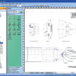
The Piping Diagram may be created on a blank sheet or overlaid on an intelligent backdrop. For example, the backdrop may be a general arrangement plan created using Aveva Space Manager (see Fig. 2). A component placed in a particular compartment or other space on the plan will automatically inherit relevant properties assigned to that compartment.
Intelligent off-page connectors are used to create logical connections between objects on different sheets of piping diagrams, or between different locations on the same sheet. Built-in consistency checks across one or more diagrams ensure, for example, that identical bore sizes are used for pipes and fittings and that defined flow directions are consistent.
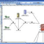
Defining a piping system using database objects rather than drawing elements enables other views of the system to also be created. The schematic model view, for example, automatically displays the connectivity of all the components making up a system (see Fig. 3). This particular view can help systems engineers to ensure that the overall process is correctly defined, and help the commissioning or validation team to better understand the systems they need to commission.
But perhaps the most important benefit of using a database-supported diagram system is that the data in the database can much more easily be checked for consistency with any other associated information (see Fig. 4).
Pipework model
The three-dimensional layout of the piping and components within a vessel is typically carried out using a 3D modelling tool that stores the information in a database. Many mechanical CAD tools used in the manufacturing industries store the created geometry as surfaces or volumes. In contrast, object-oriented systems such as Aveva Outfitting store only the information defining the object, together with attributes describing the object’s characteristics. This allows such systems to handle much larger amounts of data representing correspondingly larger and more complex structures and piping arrangements. But it also provides direct correlation between the data created in the piping diagram and that required to create the 3D pipework model.
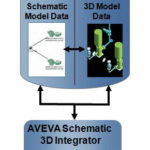
Aveva Schematic 3D integrator has been designed to exploit this correlation by maximising the efficient re-use of data that has already been defined by the systems engineer. Almost everything required to create the 3D pipework model may already be available in the database, for example:
• piping specifications describing allowable pipe material and sizes, insulation requirements and so on;
• a catalogue of components and fittings used in the piping system, including their 3D representations and connection points;
• end to end topology of system connections, including component connections, fittings, branches, in-line components and so on.
The only information that has not so far been defined is the X, Y, Z locations of the components and, naturally, the routes of the pipes themselves. But, by creating the piping diagram on the backdrop of a general arrangement plan or any other sectional drawing from Aveva Space Management, even this information will be known, at least approximately.
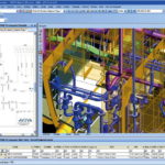
Automated functionality can position the components at their approximate locations in the 3D model, ready for final adjustment. Pipe routes between components can then be created using the modelling tools. The use of a combined database for the storage of both schematic and 3D pipework model data enables pipe route creation to be a semi-automatic, system-assisted process, thereby saving design effort and avoiding inconsistencies between the model and the piping diagram (see Fig. 5).
Unlike other manufacturing industries, it is common for shipyards to begin production of a vessel well before its design is complete. Frequently, not all necessary information is available when the piping diagram is first created. The diagram may not even be available at the start of 3D modeling. The type or size of components or the topology of the pipe route may have been modified in the 3D model. How can one ensure that the information remains consistent and accurate between the piping diagram and the 3D model as the design evolves?
Aveva Schematic 3D integrator gives piping engineers direct access to the information in the piping diagram. Using this module, the piping designer can, at any stage in the project, compare the schematic with the 3D model and identify all discrepancies and any missing data. This further helps to reduce man-hours spent in detailed design and in later design modifications (see Fig. 6).
Using such modern tools, 3D pipe modelling becomes a highly-facilitated process with many functional aids available to the piping designer, including:
• fully automatic routing or auto-completion of manually started pipe routes;
• automatic selection of appropriate gaskets and flanges at spool ends;
• automatic clash detection to identify hard and soft collisions between manually routed pipes and other components and hull structure, taking insulation, and access and equipment removal paths into account;
• a two-way interface to pipe stress analysis programs;
• integrity checks to ensure compliance with configurable defaults for minimum pipe length and to identify any incomplete or misaligned end connections;
• pre-production checks to ensure that the design suits the capabilities of the specific pipe bending machines to be used;
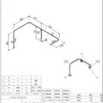
• automatic creation, direct from the project database, of production deliverables such as piping isometrics (see Fig. 7) and BoMs, pipe sketches, arrangement drawings and numerical control data for the control of pipe-bending machines.
As the pipes are created in the 3D model, the early BoMs defined in the planning system can be updated with the latest as-designed information and the original purchasing requirements reviewed. An interface between the modelling system and the planning and materials system ensures a seamless transfer of the updated BoMs.
Integrated hull and outfitting assembly production
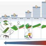
A shipbuilding project is a complex process with demanding time and cost pressures. A central task in this process is the planning of an optimum assembly sequence for hull and outfitting items. In particular, it is important to plan the installation of outfitting items at the earliest possible assembly stages; it is invariably much easier and more cost-effective to weld and install a pipe at an early block assembly stage than it is in the dock or at the outfitting quay. Aveva Assembly Planning provides production engineers with a powerful tool to increase production efficiency by maximising the amount of pre-outfitting at each stage of assembly (see Fig. 8).
Summary
An integrated shipbuilding solution has the potential to offer significant improvements in efficiency and a corresponding reduction in cost and delivery time. A high level of integration between the engineering, system design and 3D modelling enables information, once created, to be re-used in downstream design and fabrication processes. The ability to repeatedly verify the consistency of the information used in both the piping diagram and in the 3D pipework model allows errors to be eliminated before they reach production.
Aveva’s integrated shipbuilding solution provides a central repository of project information. It gives real-time access to project data and documents, enables effective collaboration, manages change and supports informed decision making.
Moreover, it permits information to be securely used across global multi-site projects, via the Internet or within an organisation’s own networks. This is a key enabler for a shipbuilding industry that is increasingly reliant on subcontracting and outsourcing, and sees increasing opportunities for collaboration on more complex projects. All these capabilities enable greater efficiency in today’s highly competitive shipbuilding industry.
Author: Andrew Gordon
Regional Manager – Marine,
AVEVA GmbH
Andrew.Gordon@aveva.com
Andrew Gordon


