Part two of the GL COMPIT Award 2012 winning paper »The Development of Modelling Methods and Interface Tools Supporting a Risk Based Approach to Fire Safety in Ship Design« by Richard Pawling et alia
4. Development of a ship product model (SPM) specification
4.1 The need for a SPM specification
Each of[ds_preview] the analysis activities outlined in Section 2 of this paper (see part one in HANSA 6/2012) has a corresponding software tool, with required input and output data. As each of these tools is analyzing the same ship design, it is important to ensure that the information required is stored in a database and managed to ensure availability and consistency. This common database is the SPM, which serves as the main vehicle for information on geometric and numerical attributes of the ship design. There are multiple ISO standard product models of ships for different applications, such as AP 215:2004 (ISO, 2004), so a new specification could be produced for the incorporation of a risk-based approach to fire safety.
4.2 The approach to developing the SPM specification
Product model specifications can be very detailed, allowing their direct implementation in software tools etc. The aim for the SPM task within the »Fireproof« demonstration was not to develop such a detailed specification, but rather to identify the contents, concepts and modelling techniques that would be required of a future more detailed specification. This development was carried out by a process of increasing focus and detail, which also contributed to the division of labour in the demonstration activity.
1. A very broad survey of the input and output variable of all the analysis tools in the »Fireproof« framework was undertaken. This included information on the analysis task they were used for, as well as units, file formats used (where tools already existed) and a statement of what the variable actually represented.
2. This information was grouped. The grouping was primarily conceptual (i.e. what is the information used for) but a process of identifying duplicate entries (where two tools had specified the same information in a slightly different manner) was also carried out. The resulting groups were:
• Parameters directly related to ship
design:
– Geometry: related to the general arrangement of the ship;
– Space specification: for each space represented in the SPM, other parameters will have to specified, such as: SOLAS category, identification, deck, zone, etc.
• Parameters not directly related to ship design:
– Parameters associated to the fire scenario and fire simulation, such as time of event, vessel location, weather contribution, ignition space, crew status, etc.
– Evacuation modelling parameters, such as the evacuation plan and fire control plan.
3. There was then further consideration of the likely information sources and flow in a ship design process. This indicated that some of the non-design parameters, such as evacuation plans, may be considered for storage within an otherwise design-oriented SPM, as they may be developed in parallel with the design configuration.
4. This consideration of the broader process led to the identification of four main types of information to be stored in and extracted from the SPM:
• Shape geometry: the shape and location of the space
• Connectivity: doors and other openings connecting spaces
• Physical properties: properties of the space, e.g. perimeter, ventilation capacity, fuel load, etc.
• Operational properties: evacuation plans, etc.
4.3 Implementing the demonstration SPM
With the types of information identified, methods were developed to represent these in the »ParaMarine«-based SPM and transfer them to the simulation tools. There were a number of aspects to consider during this development. The information needed to be represented in the SPM in an explicit, unambiguous and consistent manner to allow automated processing. In addition to these technical requirements, there is the more general need for simulation-based analysis to make use of information that is available in the design process, without creating an additional modelling workload, particularly at the early stages in design. The counterpoint to this is that, with careful consideration of design processes, modelling for simulation may assist in managing information already implicitly defined, or may use existing multi-disciplinary models.
5. Interface developments
To facilitate the data flow from the SPM to the simulation tools, a user interface was developed that interrogates »ParaMarine« and outputs the ship model data in a format that can be read in by »SmartFire« via an interface tool called »»SmartFire Scenario Designer«. This section describes the data flow from the SPM to the simulation tools and explains the technical features of this interface.
5.1 Data flow in the software framework
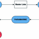
The data flow is shown in Figure 6. The blue/red ovals denote software, whereas the white rectangles stand for files. The exchange of information with »ParaMarine« is explained in the following sections.
5.2 Choice of interface tools
The user interface is built in Microsoft Access. MS Access is a relational database management system. While it is typically utilised to create small, local databases, it can also be used as a programming environment for VBA. The main reason for the choice of MS Access in this project is the fact that it can easily import and manipulate the Excel files being used to provide the master lists shown in Figure 6. However, it must be stressed that any other software or programming environment can be utilised to implement the data flow.
5.3 Building an external model of the SPM structure
As described in Section 4, several different types of objects were stored in the SPM, such as spaces, doors, stairs etc. Each of these types of objects require different sets of information to be represented in the »SmartFire« and »MaritimeExodus« models, and this information must be extracted from the SPM. In general terms, this information can be extracted by either processing an output file from the SPM or by injecting targeted queries into the SPM which return the required data for the specified objects. The latter method has the advantage of not requiring new file types in the SPM software, but does require a communications interface or API.
The »ParaMarine« software provides »sockets« over which data can be imported and exported, and can exchange information using the Microsoft COM model. However, this API functionality requires network communication between software, which was not possible in the »Fireproof« demonstration, hence a pre-existing »ParaMarine« macro/scripting language (KCL) was used to inject large groups of commands and extract large sets of output data. For future applications, the more advanced communications methods would replace the white boxes in Figure 6.
To generate the queries, the internal structure of the SPM must be available to the external interface software. The software-to-software communications methods permit structured searching of the SPM hierarchy, but with that unavailable an alternative was used. A key feature introduced in the software implementation to support this was the concept of a topological identifier. This is a numerical characteristic which flags the object as a space, sub-space, door etc. and allows the appropriate information to be exported for each type. That allows many different types of design entities to be supported. With each object in the design structure explicitly identified by type, it was possible to produce Excel lists representing the structure of the design. These were known as »master lists« and acted as an index to the structure of the SPM, containing the hierarchical names of the objects but no further details. With the design sorted in this manner, type-specific sets of queries can be generated.
5.4 Geometry transfer versus geometry reconstruction
It is important to note that the geometry itself was not transferred from the SPM to the simulation tools. Instead, characteristics of the spatial entity (door, ladder, etc.) were extracted and used to regenerate the geometry in those tools.
This is significant in that it eliminates – or at least significantly reduces – the likelihood of encountering degenerate or unmeshable geometries. These can occur if native geometry is exported between different CAD tools using different modelling paradigms (e. g. tetrahedral volume versus NURBS surface etc). This was a significant enhancement over previous integration efforts using »ParaMarine« (Andrews et al, 2008) which used 2D DXF geometry to export. The second major advantage is that this allows the regenerated geometry to be explicitly assigned numerical characteristics (such as names, population, etc.), rather than attempting to detect spaces within a DXF model or other file type.
5.5 Software interface and data exchange process
With reference to Figure 6, the process of extracting data from the SPM can be outlined as follows.
Step 1 – Produce master lists from »ParaMarine«: A list was produced for; spaces, subspaces, doors, stairs, muster stations, open spaces, zones and obstructed areas. For the purposes of the »Fireproof« demonstration, the master lists were generated manually, by pasting KCL files into Excel. This could be replaced by direct software-software communication in general application of the »Fireproof« method.
Step 2 – Produce query file from master lists: The user interface, written in MS Access, performs this task. It automatically produces a KCL query file based on the objects in the master lists. This file can be used to obtain all the required information from the SPM. The queries are tailored to the type of object represented by each list (e.g. a space requires additional information compared to a door).
Step 3 – Produce output KCL file from »ParaMarine«: The query file produced in the previous step is used to obtain all the necessary data from the SPM and store it in an output KCL file.
Step 4 – Import data into »SmartFire Scenario Designer«: The KCL output file is imported into the »SmartFire Scenario Designer« tool. This software was enhanced in the project to process the data in the KCL file and regenerate the ship model.
5.6 The »SmartFire Scenario Designer«
The »SmartFire Scenario Designer« software is utilized as an intermediate step for generating geometries for both the »SmartFire« hybrid model and »MaritimeExodus«. This reduces the overall amount of work required to generate both simulation geometries and also allows a consistent transfer of data between the SPM and simulation models. There are two major difficulties associated with building geometries for these models. The first is simply the time required to extract the information from a ship general arrangement (GA) drawing into a model within both »SmartFire« and »MaritimeExodus«. The second difficulty is transposing the atmosphere generated by the »SmartFire« hybrid model and imposing this upon the evacuation simulation of »MaritimeExodus«.
The first difficulty has been tackled by defining an SPM within »ParaMarine« that generates suitable data. To this end, a parser has been created to interpret the »ParaMarine« output file produced via the user interface. By utilising the (relatively) data-rich KCL format from »ParaMarine« and implementing the reader within »Scenario Designer«, the previously tedious task of trying to interpret 2/3D DXF files in a manual fashion has been significantly reduced and leads to a more accurate transfer of information between the tools.
The second issue has been resolved by using the scenario designer to import the data generated in »SmartFire« into »MaritimeExodus« using matched locations within both tools. Furthermore, the »Scenario Designer« would automatically create zones for data sharing if zones were not suggested by the user, which significantly reduces the workload of the user in preparing this data transfer. This facility was implemented as part of the »Fireproof« project.
6. The ship product model
6.1 The »ParaMarine« SPM implementation
This section reviews the methods used to represent the main elements of the ship design in the »ParaMarine«-based SPM demonstration. Although some issues are specific to »ParaMarine«, this section concentrates on the more general methods of modelling that would be applicable for any chosen tool. As the »Fireproof« project is intended to lead to wider applications, consideration was given in the demonstrator to the potential to automate aspects of modelling and, in particular, that which might primarily be required for analysis of the design using the »Fireproof« framework.
6.2 Geometry
6.2.1 Simplification of the model
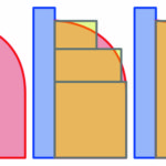
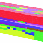
The simulation tools utilise a simplified representation of the ship, defined by axis-oriented cuboids. Complex shapes in the example model have to be discretised as cuboids. A generic example is shown in Figure 7. Simple spaces, such as passageways, can be represented by single cuboids (blue in the figure). More complex spaces, such as the red polygon in the figure, must be approximated by a series of smaller cuboids, which are explicitly grouped together as child sub-spaces of a parent space.
This method raises the issue of how to convert arbitrary geometries to cuboid representations. Here parallels can be drawn with meshing both for CFD and FEA. It was concluded that, with a digital SPM, such an algorithm could be easily applied, as the basis geometry is explicitly defined in the software model. The development of such an algorithm is driven by the needs of the simulation software and is a task for any future development. For this demonstration, the simplification was carried out by hand.
6.2.2 Representation of boundary thickness
Internal spaces on real ships are smaller than the »metal to metal« dimensions shown in GA drawings. Floors are raised by seatings, ceilings are lowered by ducts, and walls are covered in acoustic and thermal insulation. This thickness reduces the internal volume of the space, which is important when simulating a fire. This was included in the SPM using characteristics representing the thickness of ceilings, floors and walls. That represents the reduction in internal volume, not the material thickness itself, as a typical boundary will be composed of several layers of material and space. A possible future option is the use of »rules-based« logic to automatically apply this thickness based on SOLAS space category. This kind of »rules-based« population of a simulation model would reduce the time required for simulations and is enabled through a clear and explicit SPM structure.
6.2.3 Obstructed areas and open spaces
Four types of space were considered in total: space, sub-space, obstructed area, and open space. An obstructed area is a finite area within a larger space which is obstructed to a finite height. An example is where several areas of a dining hall are enclosed by railings. An open space is any space that is open to the outside air (e.g. balconies and external walkways). These are still represented as cuboids, but the faces non-coincidental with any other cuboid face can be deleted and connected to the external air representation in the CFD model. This is also amenable to automatic processing.
6.3 Connectivity
Connectivity refers to doors and other openings, ladders and stairs that are used in the personnel movement and CFD simulations. Doors and openings are defined using the same method, with ladders and stairs using a derivative method. In both cases, two types of information are needed: connectivity and characteristics. Connectivity is defined as a pointer to each of the spaces: the door, opening, ladder or stair joins. This allows the post-processing tools to detect the coincident faces of those two spaces and insert an opening of the required size. The characteristics of the connectivity item are such properties as: width of doors, type (single, double, opening with no door), and height of stairs. Connectivity is an important concept as it may not be explicitly defined in the early stages of design – the human designer knows that there must be a door, but has not placed it yet – but is required for a range of simulation analyses. There is potential for automated generation of connections between spaces based on type (e.g. a cabin must have a door to a corridor), but this would not be applicable in all circumstances (e.g. dining halls).
6.4 Characteristics
One of the advantages of the »ParaMarine« software is that an arbitrary number of numerical (or textual) characteristics can be added to a DBB object. This allowed the many ship design characteristics required by the simulations to be added to the SPM.
6.5 Muster stations
Muster stations are relatively simple to define. Conceptually they are a tag stating that a certain number of people can be accommodated in a host space. The muster station itself has no geometry. As such, the muster station entities have a capacity characteristic, a location in 3D space – set to be the centroid of the host space – and a pointer to the host space.
7. Demonstration
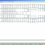
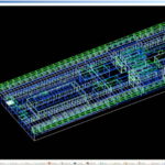
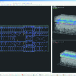
The SPM and interface tools were used as part of the modelling process to allow a campaign of simulations to be carried out. Figure 8 shows the »ParaMarine« model, which represented two zones of a generic cruise ship. This model contained 2,451 objects, including 1,263 spaces and 1,117 connectivity items. Figure 9 shows the same geometry in the »SmartFire Scenario Designer«, Figure 10 shows it in »MaritimeExodus«, and Figure 11 is an isometric view of a single deck in »SmartFire«.
The prototype interface successfully imported approximately 95% of the model, with correction necessary for modelling errors in the SPM and limited import errors.
8. Future developments
Several areas for future development were identified for investigation beyond the current »Fireproof« project. These include:
the incorporation of the complete range of analysis tools – as this work focused on the CFD model –, the use of an analysis automation environment to streamline the transfer of data between models, and a move towards a more detailed specification of the SPM and data transfer methods – similar to ISO standards.
9. Summary and conclusions
The »Fireproof« project is developing a probabilistic, risk-based approach to fire safety for passenger ships that will allow the rational assessment of risk for both conventional and novel designs. This project has seen the development of modelling and analysis tools addressing all aspects of fire, from ignition to spread and consequences for the passengers and crew.
To support these analyses, including simulations using a new hybrid CFD / Zone model, the basis specification for a ship product model (SPM) has been developed. This SPM has been demonstrated using the »ParaMarine« software, and data has successfully been transferred to the analysis tools using interface software. The object-oriented description of the ship design used in the »ParaMarine« software was found to be very important for the development of the SPM, as it allowed multiple new characteristics to be associated with spaces in the design. In addition to the conceptual and practical issues of data types required for analysis, broader considerations were found to be important, including the availability of information in the ship design process and organization, the effort required to describe the design data in an explicit manner, and the potential for automation.
10. Acknowledgements
The research reported in this paper is partially funded by the »Fireproof« project
(under Grant Agreement 218761) as part of the 7th Framework Surface Transport Programme of the European Commission, a contribution that is gratefully acknowledged by the authors.
Richard Pawling, Angus Grandison, Philipp Lohrmann, George Mermiris, Claudia Pereira Dias


