Ship positioning technology is only as precise as incoming control signals. To bridge this gap, the new Becker Intelligent Monitoring System based on timely measurement of rudder forces has been developed. Andreas Linger reports on its operation
Modern dynamic positioning systems (DP) and autopilot systems (AP) utilise a variety of input signals to maintain course or position[ds_preview], e.g. from positioning reference sensors, combined with wind sensors, motion sensors, gyro compasses, GPS data etc. These data are processed by an IT system to allow the course or drift to be predicted and to calculate countermeasures controlling the actuators in the vessel’s propulsion system. Input data and processing is of high quality, but only reflects the vessel’s motion response. Inertia causes a massive decrease in the strength of these control signals, which do not meet or provide sufficient quality for manoeuvring in manual or automatic steering mode. The rudder force generated for specific rudder angles is not available to the ship’s navigation system and the crew. Especially when sailing in coastal and high-traffic areas knowledge about the generated rudder force at different rudder angles is vital.
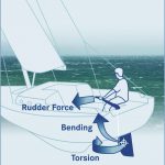
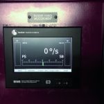
The problems described above were addressed by Becker Marine Systems to provide a solution. To improve manoeuvrability during automatic and manual steering there is a need for timely and direct measurement of rudder forces, which currently allows the generated rudder lift and resistance to be determined. For this purpose, the Becker Intelligent Monitoring System (BIMS) has been developed. It is able to directly calculate rudder forces by measuring the bending of the rudder stock and to interface them with the ship’s navigation systems as well as visualise rudder lift on the bridge. Rudder force measurement can figuratively speaking be compared to the principle of a sailor who keeps his sailing ship on course by simply feeling the rudder force on the helm and not by applying specific rudder angles.
This well-known principle is now transferred by BIMS for use in merchant shipping. The system thus improves manoeuvrability and allows energy-saving autopilot operation by reducing rudder movements and more efficient dynamic positioning.
Rudder force measured by BIMS can be utilised for various applications:
Case 1: Efficient dynamic positioning
Ship operators in the offshore business using conventional rudder-propeller arrangements in their vessels are always looking for ways to improve DP performance. This is because there are many advantages to using a main propeller and rudder instead of azimuth thrusters. These include there being no limitation in installed power, good response times and high course-keeping performance.
For this reason, Becker Marine Systems (BMS) and Kongsberg Maritime (KM) began a joint development project utilising their respective expertise in high performance rudder systems and DP systems to enhance DP capabilities. Due to nature’s influences of wind, waves and current the operational conditions of a rudder vary significantly at any one time. Even in steady conditions the correlation between the angle of attack and lift is non-linear. For BMS and KM the challenge was to find a more direct indicator of manoeuvring performance than the vessel’s motion reaction detected by GPS or gyrocompasses.
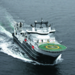
It turned out that the closest value to describe performance was the rudder force itself measured by the new BIMS. Integrated into Kongsberg’s K-Pos DP system the product is marketed under the name KBIMS. The first KBIMS was installed on Volstad’s new offshore construction vessel (OCV) »Grand Canyon« end of 2012. On this twin-screw vessel each of the both rudders is equipped with Becker’s rudder force measurement device. After installation the system was intensively tested and improved under operative conditions in the North Sea for several months. This enabled Becker and Kongsberg to approve the theoretical system parameters and algorithms which have previously been developed in the R&D departments of both companies and to add improvements based on the practical experiences gained during the sea trials. Integrated into K-Pos, the monitoring system learns the characteristics of the rudder so the correct combination of rudder angle and propeller pitch/rpm is used for DP. Exact measurements of the actual rudder force secures improved station keeping performance. More precise rudder control will reduce wear and tear of steering gear, rudder stock, and bearings, so less downtime and maintenance costs are possible. Furthermore, there is a significant reduction in rudder flipping and manoeuvring hysteresis around a fixed position in DP mode leading to power savings and emission reductions.
Case 2: Safer manoeuvring
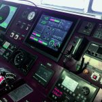
On Hapag-Lloyd’s new 13,200 TEU »New York Express« BIMS was installed in November 2012 including a display on the bridge indicating rudder forces to the crew. In order to evaluate the full potential of the system and to familiarise the crew with the now available rudder force data, extensive sea trials and data analysis have been made on board showing impressive results.
Up to now the effectiveness of the rudder could only be reflected by the delayed vessels response to the applied rudder angle. By displaying rudder force to the Officer of the Watch, the BIMS ensures optimal rudder performance for safely manoeuvring even in shallow, coastal or restricted waterways. The ship’s crew is now able to detect rudder forces, indicating where poor rudder response or even rudder stall can be expected under current manoeuvring conditions. This enables the Officer of the Watch to take appropriate counter measures in advance, by applying the optimum rudder angle to achieve maximum rudder force and manoeuvrability especially in emergency situations such as collision avoidance. But not only can the rudder force be monitored. Due to the measurement principle used by BIMS also the forces acting on the ship itself could be detected. Sea trials on the River Elbe near Hamburg showed that the BIMS rudder force display is also capable to indicate the sway force acting on the ship due to a banking effect in narrow waterways. Thereby a dangerous bank effect can be detected in advance to ship’s reaction on it enabling the crew to take counter measures in time.
Case 3: Energy-saving autopilot operation
Travelling at a speed of 14 kn on autopilot, the rudder of a 100,000 dwt tanker for example moves continuously within a range of +/- 5 degrees, leading to a significant
increase in fuel consumption. Direct force feedback made available by measuring rudder force, interfacing the BIMS to a ship’s autopilot system, offers the potential to significantly reduce rudder movements in autopilot mode.
Decreasing control of rudder operation along with increasing manoeuvrability can result in energy savings of about 1–3 % with a corresponding reduction in emissions of CO2, NOX and SOX which is also in accordance with Article 5 of the Ship Energy Efficiency Management Plan (SEEMP) giving guidance on best practices for fuel-efficient operation of ships by optimum use of rudder and heading control systems. Becker Marine Systems is working together with renowned autopilot makers to realise above mentioned fuel saving potentials by interfacing rudder force data into the ship’s autopilot.
Author: Andreas Lingner
Project Manager BIMS
Becker Marine Systems, Hamburg
anl@becker-marine-systems.com
Andreas Lingner


