


Ships rely on reliable mooring systems. The Fraunhofer Centre for Maritime Logistics and Services has developed a software tool to analyse mooring systems, identify potentially dangerous situations and provide safety recommendations for given weather conditions
There are several possible reasons for analyzing mooring systems. Common examp[ds_preview]les include newbuilding or alteration of harbour infrastructure, handling of project cargo or a rededication of piers to different types or sizes of ships. Independent from the motivation, the goal always is to ensure that the ships remain safely moored under the given environment conditions, since the failure of a mooring system can have severe consequences. To name a few, breaking lines and a drifting ship can be a lethal threat to harbour workers and ship crews and is likely to cause further accidents and damage to other ships and infrastructure. At the very least it will cause an interruption of operations in the harbour.


New software tool
The failure of a single line can cause a whole mooring system to collapse. It is thus crucial to understand which elements of a mooring system carry the highest loads and are thus most prone to breaking. In order to gain this insight, Fraunhofer CML has developed a software tool to compute the individual loading of lines, fenders and bollards that are part of the mooring system. The tool is inspired by the Mooring Equipment Guidelines (MEG) of the Oil Companies International Marine Forum (OCIMF), but is applicable to any type of ship. The software considers three degrees of freedom, surge, sway and yaw. The first module contains the external loads acting on the ship and the second the structural model of the mooring elements. Within the external load model aerodynamic and hydrodynamic forces and moments are determined, taking into account the individual characteristics of the ship. Due the modularity of the tool, further external loads can be added.
In the structural module all mooring elements like lines and fenders are modelled as elastic springs in three-dimensional space with individual stiffness properties. Since lines and fenders can only be subject to tension or compression, respectively, provisions are made for lines becoming slack and fenders losing contact with the ship hull. Because of the significant influence of the total length of each line on its elongation characteristics, great care is taken to capture the paths of lines around all deflection points. The ship itself is modelled as rigid body.
A system of equations
The combination of the external loading and structural modules creates a system of equations which is solved according to the following sequence. First the external forces and moments are determined. In the second step the overall spring stiffness of all mooring elements is derived for each degree of freedom.
From external loads and spring stiffnesses the expected displacements of the ship can be calculated. However, the displacements are not independent of each other. For example, a movement of the ship in longitudinal direction changes both longitudinal and transverse force components that a line exerts on the ship.
As a consequence, the solution can only be found in an iterative process. Hence, after applying the calculated displacements to the ship, the coordinates of attachment and deflection points of the lines and fenders are updated. Using this information, the lengths of the mooring elements can be calculated from which the exerted loads can be derived.
The overall mooring loads can then be compared with the external loads. From the difference between the two in combination with updated spring stiffnesses, new displacements of the ship are calculated and the process starts over. This sequence is repeated until the difference between external and mooring loads falls below a set threshold.
Offshore winds deemed critical
The following case shows an example of how the tool can be used to define wind limits and optimize mooring configurations. The initial situation was a reassignment of a 100 m PCTC to a berth that had not been used previously as it had limitations in terms of the mooring infrastructure. In particular there was no bollard available forward of the ship which caused concerns.
The client Niedersachsen Ports wanted to ensure that the loads on the available bollards stayed inside safe working load (SWL). Additionally, wind limits were to be established if the SWL was exceeded. Considering these requirements, a simple mooring arrangement was designed with lines deployed from the starboard corners of the ship to each bollard. Forelines could not be deployed due to the lack of a suitable bollard as mentioned above.
To determine the wind limits a matrix of eight wind angles and six velocities between 10 kn and 60 kn was defined. Hydrodynamic forces were not considered. An empty ship was deemed the worst-case scenario as it maximizes the windage areas and gives the most unfavourable lead angles for the mooring lines.
In the results analysis it was observed that on-shore winds from between 180° and 0° could generally be considered safe independent of wind strength. In contrast offshore winds blowing from 45°, 90° or 135° were deemed critical or unsafe when 30 or 40kn of wind were exceeded, respectively. The loading of the forward breast lines becomes critical at 40kn of wind with subsequent overloading at higher wind velocities. At a windspeed of 60kn the aft breast lines and one of the aft springs is also exceeding 50 % SWL.
Changed wind limits
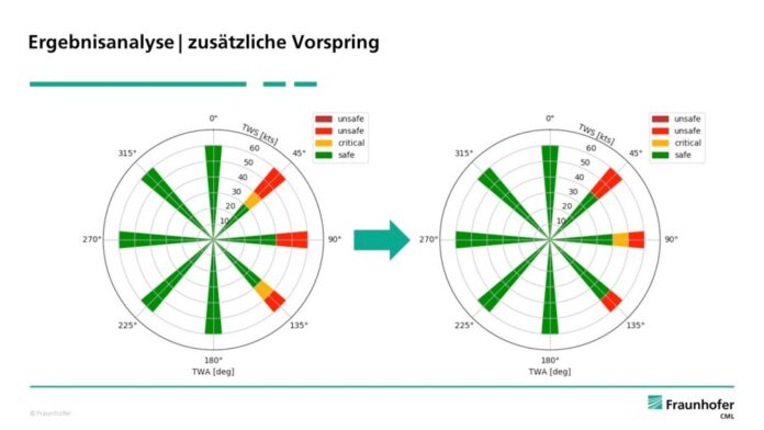
There are several options for optimization of the mooring arrangement towards increasing the wind limits. One intuitive approach would be to strengthen the weakest parts of the system, in this case the forward breast lines. However, due to their athwartships alignment, the breast lines cannot exert significant longitudinal forces which is assumed to be part of the problem. Instead it was chosen to reinforce the aft springs since they are the only elements that can absorb the longitudinal loads. This also compensates the imbalance in the longitudinal stiffness between aft lines and forward springs on one side and the aft springs on the other side.
Reinforcing of the aft springs caused changes in wind limits. Conditions are considered critical (orange) if 50 % of the SWL of any line is exceeded and unsafe (light red) above 60 % SWL, which corresponds to the typical setting of the mooring winch breaks. Dark red would indicate an overloaded bollard. It can be seen that the wind limits have been increased slightly. At a wind angle of 45° the previously critical rating for winds up to 40 kn has disappeared. At 90° winds of up to 50 kn are now considered critical but not unsafe and at 135° they are now considered completely safe.
In this case the mooring arrangement was analysed and subsequently optimized for higher wind limits. Another option would be to minimize the number of lines for given wind limits to speedup mooring operations, reduce turnaround times and increase berth utilization. In this context site specific wind statistics could also be considered in the future.
Author:
Nils Hagemeister
Fraunhofer-Center für Maritime Logistik und Dienstleistungen CML